Wednesday, September 7, 2016

Pong Game: Joystick Controlled

This version of the Pong Game builds on the previous, but the paddles are controlled by a logitech controller's two joysticks.  This version of the game is for two players, each of which control one of the joysticks.  The game keeps track of the number of times that the ball has hit each player's paddle and displays this score on the screen.

Currently the program does not end nicely; there is a Null Pointer Exception which terminates the run when the ball runs off the edge of the screen.   I am not sure on the source of the exception.

The video below shows the game being played.

Much of the code is the same as the previous post including the classes Ball, Paddle, and ButtonListener.  The class Listener is similar, but now the mouseMoved method doesn't do anything.  GamePanel now includes two more labels which display the player's scores (scoreLabel1 and scoreLabel2).  It is also passed a JoyStickController object which gives axes to the method GetYAxesValues and the variables Y1Value and Y2Value which contain the most recent values of the two joysticks on the Logitech Controller (more on that below).


The picture shows that the left and right paddles' ycor variables are set to increase with the value of the left and right joysticks on the Logitech controller (respectively).  So if the left joystick is centered (Y1Value is zero), then leftPaddle.ycor stays constant.  If the left joystick is pressed up, then Y1Value is negative and leftPaddle.ycor decreases causing the leftPaddle to move up on the screen (recall that the y-coordinate increases as you move down the screen).  If the left joystick is pressed down, then Y1Value increases and the leftPaddle moves down the screen.  The multiplier *20 just makes the paddles move at a reasonable rate.

The class JoystickController includes two methods, SetController and GetYAxesValues.  The first method is called once when the main method of the PongGame class is run, and it scrolls through all the attached devices looking for one of type "Stick" .  It then sets a local variable (logitech) of type Controller to be that device.

The GetYAxesValues method calls a Controller method called poll, then sets an array called components to include the names of each of the parts of the Logitech controller.  It scrolls through the components array until it finds the array element called "Z Rotation" then stores the value of that component using getPollData in Y1Value.  Similarly, it stores the value of "Y Axis" in Y2Value.  Each value is subjected to a deadband, so that if the value is between -0.1 and 0.1 it is set to 0.

In the PongGame class, most everything is the same, but the main method now just creates an instance of PongGame, then called two methods (setupPlayers and initializeGame).  This is a much more elegant way compared to the mouse version, which does all the work in the main method.

Full game code can be found here:  https://github.com/gcronin/PongGame/blob/JoystickControl/PongGame/src/ponggame/PongGame.java .

Tuesday, September 6, 2016

NXT Security System

MIT App Inventor 2 is a great tool to develop Android apps.  It also has some robotic functionality as there is built in support for LEGO NXTs and EV3s.  I just finished a very small test program to try out this functionality.


I wrote an app which uses a light sensor and sound sensor on an NXT to simulate detecting an intruder. The light sensor normally has a laser pointer flooding the input, but if something crosses the path of the laser, the light reading drops much lower. This triggers an alarm which is indicated by a moving motor, a beeping sound, and a visual indicator ("Alarm!") on the Android phone. Similarly, a sound above the threshold (set at 125) on the sound sensor trips the alarm. The Android interface allows you to turn on and off the alarm, shows the values of the sound and light sensors, and shows whether you are connected to the NXT.

When creating an app in MIT App inventor, you first create the interface (Designer) then create the code (Blocks).  Coding is drag and drop just like Scratch or Enchanting.   The interface for this app is shown below:

There are several button to connect and disconnect to an NXT over Bluetooth, and to turn on or off the security system.  There are also several NXT specific objects: an NXT Sound Sensor, an NXT Light Sensor, and an NXT Direct Commands (which gives access to motor control).  A clock is setup with a one second increment.  Finally, there are several "labels" which are places where text is displayed.  One label (status) shows whether the alarm is on, off, or triggered.  Another label (SoundReading) shows the sound sensor reading or "not connected" if there is no Bluetooth connection.  The last label (misnamed UltrasonicReading from previous experiments) shows the light reading or or "not connected".

The coding is all event driven.  Events can be triggered by pressing a button on the App interface, by a recurrent timer, or by certain sensor criteria being met.
The Connect to Robot and Disconnect buttons give Bluetooth functionality.  When you click the Connect To Robot button (which is actually a list picker), it brings up a list of available Bluetooth devices.  When you select one, the App makes a connection to that NXT.  The Disconnect button ends that connection.

Two global variables are used to control whether the alarm is on (on?), and whether it has been triggered (AlarmTripped?).  The OnButton sets on? to true.  Once that criteria is met, either a NXTSoundSensor.AboveRange or a NXTLightSensor.BelowRange event can make the second variable (AlarmTripped?) true.

A clock event is triggered every second.  This event displays the sound and light sensor readings if there is a Bluetooth connection.  Otherwise it displays "Not Connected".  If the value of AlarmTripper? is true, it plays a tone, and spins a motor.  Because the duration of the tone is half of a second and the clock event is triggered every second, the overall aural effect is a periodic beeping sound which sounds like an alarm.

The OffButton resets both global variables to false and stops the motor.

Overall, this was a simple but great way to learn MIT App Inventor 2.  The project has been published on the App Inventor 2 website:  http://ai2.appinventor.mit.edu/?locale=en#4626597671075840.


Monday, August 29, 2016

Pong in Java: Mouse Controlled Paddle

The previous post discussed command line Java.  I went a little deeper to make two versions of the classic game Pong.  This first one uses the mouse to control one of the paddles.  The other paddle is controlled automatically by the computer.


Java is an object oriented language.  Pong lends itself to programming in this manner because the game is based on objects... specifically a ball and two paddles.  Objects in Java are instances of a class.  A class can contain its own variables, own methods (functions), and requires a constructor which describes how an instance of the class should be created.  For example, the following is the class for a ball:

Each instance of the Ball class has an x-coordinate, y-coordinate, heading, speed, and a diameter.  The diameter is always the same, but the other variables are set when the Ball instance is created.
Elsewhere in the program, an instance of Ball called "ball" is created using the command:

Ball ball = new Ball(200, 100, 30, 10);

The constructor assigns the variables for "ball" (eg its xcor equals 200, etc).

There is also a method for the Ball called "move", which changes the values of xcor and ycor depending on the Ball's speed and heading.


Another object is a Paddle.  The following is the class for a paddle.


This class is similar in many ways to a ball; it has several variables which describe its geometry, but it also interacts with a Ball, and so one variable describes a property of a Ball.

The constructor requires an instance of a Ball to be passed to it:

Paddle leftPaddle = new Paddle(0, 100, 20, 100, ball);

This is important because the "overlaps" method for a Paddle checks to see if the middle of the ball (ballycor + ballDiameter/2) is below the bottom of the paddle (this.ycor + height) or above the top of the paddle (this.ycor).  The relevant geometry is shown below.


The real action for the game happens in the GamePanel class, which includes the methods "paintComponent" and "animate".  "paintComponent" colors two rectangles and an oval at the locations of the left and right paddles, and the ball.  When an instance of GamePanel is created, the constructor requires two Paddles and a Ball.  paintComponent is a method of the class JPanel.  GamePanel extends JPanel, and I have overridden the default method paintComponent.


The "animate" methods causes the ball to move, to deflect off the upper/lower values, and to deflect off of a paddle.  It also causes the right paddle to have the same height location as the ball: rightPaddle.ycor = ball.ycor - rightPaddle.height/2;

The deflection works as follows:  we first check if the ball is within the paddle's width of the left side of the JPanel:  if( ball.xcor  < leftPaddle.width). If so, we want to know if the ball's y-coordinate overlaps with the location of the left paddle.  If so, we do some fancy math to change the heading of the ball so it looks like it bounced off the paddle.   Note that this code does not currently end the game if the paddle and ball don't overlap... the ball goes off the screen to the left, but then it will eventually "bounce" offscreen because the original "if" statement is still true, and the ball will "overlap" with the paddle at some point.  This is a bug.

Next we check to see if the ball is within the paddle's width of the right side of the JPanel:

if(( ball.xcor + ball.ballDiameter)  > getWidth() - rightPaddle.width).  

getWidth() is a built in method for a JPanel which returns the width of the JPanel.  If so, we then check to see if the ball's y-coordinate overlaps with the location of the right paddle, in which case the ball's heading is changed to Pi minus its original heading.

Finally, we check to see if the ball is either at the top of the JPanel (ball.ycor < 0) or at the bottom of the JPanel (ball.ycor > getHeight() - ball.ballDiameter).  In either case, a vertical bounce is done by making the original heading negative.

The class Listener allow the user to interact with the game through the mouse.  Listener implements the interfaces ActionListener and MouseMotionListener.  The latter gives us access to the methods mouseDragged and mouseMoved.  I only use mouseMoved (although you have to override mouseDragged ...my method for mouseDragged does nothing).


When the mouse if moved, it triggers a MouseEvent called e.  We can read the vertical location of the mouse (e.getY()) and then we position the left paddle accordingly.  If the mouse is at the bottom or below the JPanel, the left paddle stays at the bottom of the JPanel.  If the mouse is at the top or above the JPanel, the left paddle stays at the top.  Otherwise, the position of the paddle is set according to the vertical location of the mouse:

gamePanel.leftPaddle.ycor = e.getY() - gamePanel.leftPaddle.height/2;


The ActionListener interface includes the method actionPerformed, which is invoked anytime an action occurs.  Actions are occurring all the time, and so this method occurs constantly.  I have overridden the method to have it call the GamePanel.animate method discussed above.


There is another ActionListener called ButtonListener which includes a timer which is started and stopped by two buttons in the main JPanel, called startButton and stopButton.


The main class for the pong game is a JFrame class called PongGame.  It has no constructor and no instances; everything in the class occurs in the method main.  Main creates a JFrame with two JPanels.  The "top" JPanel (called settingsPanel) includes start and stop buttons.   The other JPanel is the gamePanel already discussed.

In main, we create the ball and two paddles for the left and right sides of the screen.  We create a timer which runs when the start button is pressed and stops when the stop button is pressed.  We create an instance of ButtonListener. We create a Listener so we can have the game animate and detect mouse movement.

I am still confused by aspects of the code.  I know that they work but I just stole them from online.  In particular, these lines are tough:

           Listener listener = new Listener(gamePanel);
      Timer timer = new Timer(50, listener);
      gamePanel.addMouseMotionListener(listener);
      gamePanel.requestFocusInWindow();
   
      ButtonListener buttonListener = new ButtonListener(startButton, stopButton, timer);
      startButton.addActionListener(buttonListener);
      stopButton.addActionListener(buttonListener);


The PongGame class is shown below:
Full code for this game can be found here.

Learning Java: Command Line and LeJos

FIRST switched to Android Studio for robotics coding for the 2015-16 season.  Android Studio is a Java based platform used to create Apps for Android phones.  I spent part of last summer trying to get up to speed with Java.  Rather than dealing with Android Studio (which is a whole different can of worms), I worked with command line Java, and then with Java in NetBeans.

The command line programs described below are on GitHub at https://github.com/gcronin/LearningJava.

Program 1: Parabola
This program uses the scanner to take in  the coefficients of a parabola written in standard form, and converts to vertex form.


Here's an example of the output; the parabola y = x^2 + 2x + 5 is equivalent to y = (x+1)^2 + 4 with a vertex at (-1, 4).


Program 2: Distance Formula
Using the scanner again, the user inputs the x and y coordinates of two points, and the program calculates the distance between the points.


Here's an output showing that the distance between (0,0) and (1,1) is the square root of 2.


Program 3: Add Text to a File
This very simple program requires dealing with exceptions, which is a big part of Java.  When you open and write to a file, you must catch two exceptions... the first is given if the file doesn't exist, and the second is given if the program cannot write to the file.  We deal with exceptions by using the Try... Catch syntax.

A much more complex version of this program with user input can be found here (I didn't write it).


Using LeJos:  Java for NXT:
You can program a LEGO NXT in Java.  One of my students setup the compiler for me.  Once LeJos is installed on your computer, you first need to turn .java files into .class files using "nxjc".  Then you need to use "nxjlink" to create an "nxj" file from one of your class files.  Finally, you use "nxjupload" to upload the .nxj file.  In total, this series of commands will do the work for you:

nxjc *.java  //create .class files from .java files
set /p mclass= "Please enter the name of the main class file: " %=%  //chose a .class file
nxjlink -o linked.nxj %mclass%  //create linked.nxj from the .class file
nxjupload -r *nxj   //upload linked.nxj to the NXT


Here are a few Java programs for the NXT:
 This program just prints "Hello World" to the screen until any button is pressed.
This program shows the value of a light sensor attached to port 1 in several different formats.
This program moves motors attached to ports B and C at 50% power.
This program is a line follower using PID control.  I am not sure that it has been tuned correctly, as it was written by a former student.


Sunday, August 28, 2016

Fun with H-Bridges

This summer in our school's robotics camp, participants worked with the Adafruit Mini Rover Chassis Kit.  For $25, it looks like a steal.  However, the motors turn out to be tiny DC motors and not continuous servos, and so speed control requires circuitry beyond a microprocessor.

There are three basic ways to control a motor.  If you want to simply turn the motor on and off, you can use a switch wired directly to the power for the motors.  The breadboard below shows that setup on a Parallax Board of Education Shield.


If you want to digitally control the speed of a motor (in addition to turning it on or off), you can use a transistor.  In the picture below, a bipolar 2N2222 is wired to a PWM output of a microprocessor to allow for speed control via the duty cycle.


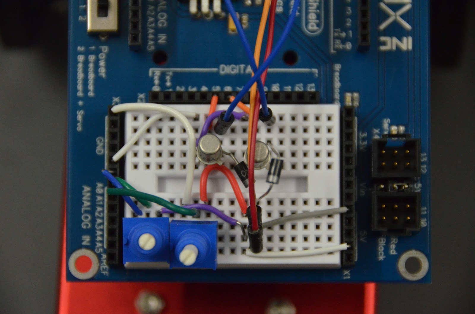
Finally, if you want full speed AND direction control over motors, you need an H-bridge.  I've made H-bridges before (see the Explorer Bot), but I figured it was time to make a simpler one which could be used for educating students using the Mini Rover Chassis Kit.


The result is shown in the picture above.  It uses two 2N2907 PNP transistors in the upper legs, and
two 2N2222 NPN transistors in the lower legs.  There are two H-bridges, one for the left motor and one for the right motor.  All eight transistors are wired to separate digital outputs on an Arduino, with the NPN transistors controlled by PWM pins.  This allows for speed control.  Potentiometers control the speed and direction in the test code.


Schematics, Eagle CAD board files, and test code is published on GitHub at https://github.com/gcronin/H-bridge.

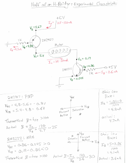
I also measured some voltages and currents for one leg of an H-bridge, and then analyzed the circuit from the point of view of both a physicist and an electrical engineer.


Thursday, May 26, 2016

Water Pump

This is a water pump fabricated from scratch based on the directions of Gerald Recktenwald at Portland State University, found here: https://learn.sparkfun.com/resources/44.  The housing was constructed from PVC plastic using a mill, mostly used as a precise drill press.  A centered N size through hole fits a bronze bushing and o-ring seat for the motor shaft.  On the other side, a 1" forstner bit is used to make the cylindrical chamber for the impeller (yellow) and a 1.25" forstner bit makes a seat for an o-ring.  On the top of the grey and the middle of the clear sheet, two Q sized holes are tapped with a 1/4" NPT pipe threads for the barbed hose connectors.  Four holes allow a zip tie to hold the motor in place.  Finally, the clear and grey pieces were attached with screws to compress an o-ring, sealing the other side of the pump from water.

The bronze bearing was fabricated on a lathe.  A through hole was drilled concentric to the outer diameter of a bronze rod.  The end of the rod was beveled to allow it to be pressed into the N hole mentioned above.  A small seat was made with an end mill to house the tiny o-ring which sealed the motor shaft from water.  The rod was then parted to make the bearing.

Finally, an impeller was fabricated on a Makerbot 3D printer from a design I created in Solidworks.  The impeller is not anything fancy, and is not optimized at all.  Part of the point of this project for students is to design their own impellers and then to test the efficiency of the pump.  Nevertheless, the pump worked when I tested it (at least as soon as i figured out which side was the inlet and outlet).

In the video below, you can see that the pump can supply a limited amount of potential energy; as the outlet tube is raised, the flow rate diminishes until its maximum pumping height is reached where the flow rate is zero.


Thursday, May 19, 2016

Simple Wearables

Just a couple of fun wearables.  All run by the Lily Twinkle which outputs random signals to four LEDs.  The LEDs were sewn on with conductive thread.  
The yellow wearables are headbands which were used by the drive team of FTC Team 5619.  The beige has conductive velcro which turns on the device when the bracelet is put on as shown in the video below.