There are three basic ways to control a motor. If you want to simply turn the motor on and off, you can use a switch wired directly to the power for the motors. The breadboard below shows that setup on a Parallax Board of Education Shield.


If you want to digitally control the speed of a motor (in addition to turning it on or off), you can use a transistor. In the picture below, a bipolar 2N2222 is wired to a PWM output of a microprocessor to allow for speed control via the duty cycle.


Finally, if you want full speed AND direction control over motors, you need an H-bridge. I've made H-bridges before (see the Explorer Bot), but I figured it was time to make a simpler one which could be used for educating students using the Mini Rover Chassis Kit.


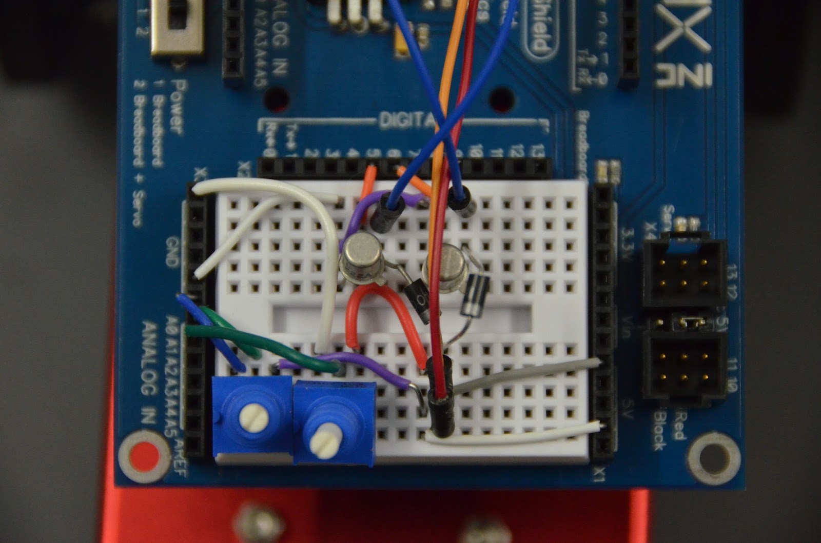
The result is shown in the picture above. It uses two 2N2907 PNP transistors in the upper legs, and
two 2N2222 NPN transistors in the lower legs. There are two H-bridges, one for the left motor and one for the right motor. All eight transistors are wired to separate digital outputs on an Arduino, with the NPN transistors controlled by PWM pins. This allows for speed control. Potentiometers control the speed and direction in the test code.

Schematics, Eagle CAD board files, and test code is published on GitHub at https://github.com/gcronin/H-bridge.
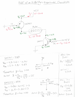
I also measured some voltages and currents for one leg of an H-bridge, and then analyzed the circuit from the point of view of both a physicist and an electrical engineer.