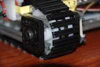


I bought the tank and tread system from Tetrix, which comes with six idler wheels for the bottom of the robot, and two sprockets which get driven by the motors. The tetrix system uses 4.7mm nonstandard axles with a flat on them. Axle lockers are used to keep things from moving. From experience with them, they are great for prototyping but they are terrible for permanent installations. I wanted a very low friction, reliable setup, so I used ball bearing mounts from Open Beam, 8mm bearings, 8mm bolts, and skateboard spacers, to mount the idler wheels between two pieces of the Microrax.

I planned carefully to fit all the electronics in an enclosed box, given that the squirt gun was going to be directly above the electronics. The Microrax setup allows for acrylic panels to be easily slid into place, so I planned carefully on the placement of the arbotix, two parrallex HB25s, the battery, the RX64s, my relay board for the squirt gun, and a new addition which was a 6DOF (degree of freedom) accelerometer and gyro I2C board from Sparkfun. I needed a little electronics board for the 6DOF, because it runs off 3.3V while the Arbortix board is a 5V device. I used an LM317 to bridge the voltage gap between those two. Interestingly, a simple voltage divider circuit did not work... perhaps the voltage was not stable enough for the electronics... the regulator was a necessity.
 |
| In the middle, you can see the 6DOF screwed into the piece of white acrylic. The relay which drives the squirt gun is just behind a tiny blue capacitor. |
Actually the battery did not fit where I had originally envisioned, which was ok. The relay board for the squirt gun and the 6DOF board (those two were attached to each other) took up a lot more space than I had planned. Fortunately, the battery fits great at the back of the robot where it is easily accessible for charging.

 |
| Here you can see that the motor barely clear the acrylic enclosure. |
Pretty much everything went together the way that I wanted. One difficulty was that the motors had to be mounted slightly higher than I had originally envisions in order an acrylic plate that was the top of the enclosure for the electronics. Another difficulty was that I needed to mount Microrax on top of each other and at right angles in order to provide structural integrity across the entire robot in the direction perpendicular to the tank tracks. This required fabricating and 3D printing a part. I used SolidWorks to create the part, exported the part as an STL file, cleaned up the part using NetFabb, generated gcode using Replicator G, and then printed the part out of polylactic acid (PLA) on a Replicator. The CAD as well as a picture of the printed part are shown below.


The other piece of this puzzle that was extraordinarily difficult came out during testing. When I ran the program, it started going back to the random glitch I had seen previously when trying out the iPad as a control device over OSC. Fairly regularly, the motors would both spin, the tilt servo would move, and the gun relay would trip. This all lasted for maybe half a second before going away. I had previously assumed that the problem had something to do with the OSC/iPad setup, but clearly with that removed from the loop and the problem still occurring, I had been wrong.
Originally the glitch went away when the Xbees were replaced with an FTDI cable. So clearly the problem had something to do with serial communication over the Xbees. I tried to move the Xbee to a more central location away from the metal aluminum, which might have been screwing up with the radio waves. This did not fix the problem. If the Xbees were the problem, then the Arduino sketch would need to be modified to detect an anomalous serial packet, and to ignore it. I tried multiple conditions, such as if(gun == 1 && tilt > 465 && motor1 > threshold && motor2 > threshold). If that criteria was met, I set the "error" flag in my program equal to one. After many many trials, I was able to screen out the problem by looking for motor powers in positive or negative direction above 90% power. Setting the error flag when this occurred removed the glitch. I modified the Processing sketch so that it no longer sent powers this big.
There is a lot to be done still on the robot, but at this point I can focus on programming. Here are the future projects:
- Get the stall check code working repeatably
- Revisit the iPad/OSC control and see if it works repeatably with the "glitch" being screened out
- Calibrate the gyro/accelerometer to do repeatable turns of known angle
- Calibrate the optical encoders to move repeatable set distances in a straight line
- Start playing with autonomous code to detect and react to obstacles based on the infrared sensors


