Tuesday, December 9, 2014

Mood Machine

Students in Seattle Academy's robotics elective worked to make and program a Mood Machine.  It is designed to be used by a classroom teacher in order to assess the overall mood of his/her class.


The students were able to describe the contributions they made to the project.


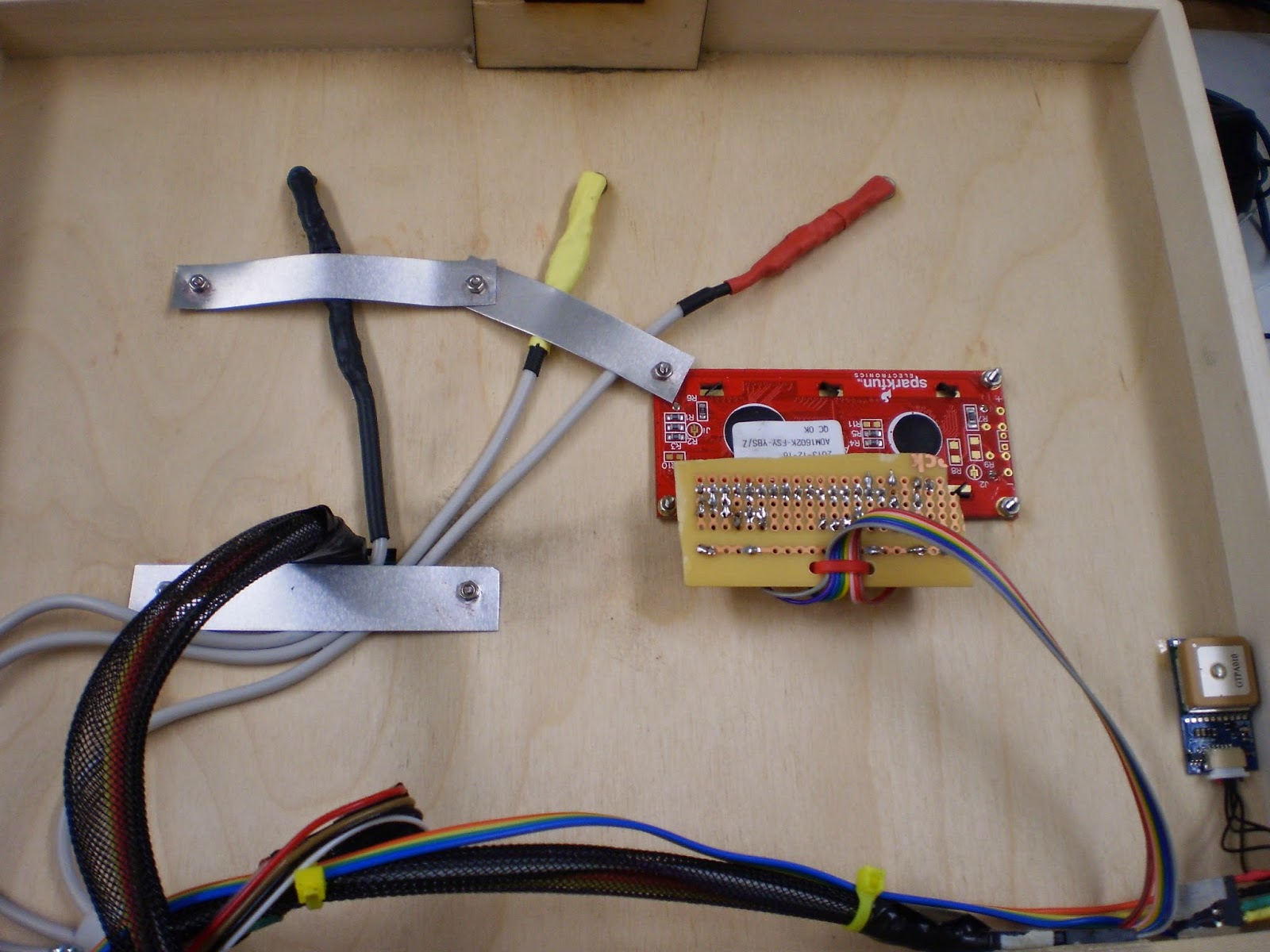
The Mood Machine was based on the fun SparkFun Big Dome Pushbuttons (COM-11275, COM-11273, COM-09181, COM-11274).  These have a LED lamp with integrated resistor (designed for 12V input), the a momentary pushbutton.  These were wired into a PCB board with pullup resistors (this was a concept we had covered in class using the tutorials at Lady Ada, http://www.ladyada.net/learn/arduino/).

The schematic below shows how the pullup resistors (10k) are used while a 1k resistor is put in series with the pin going to the Arduino Mega.  Jack put together the schematic.  All the milling files can be downloaded at this link:  https://sites.google.com/site/rampantrobots/moodmachine/MoodMachineMillingFiles.zip?attredirects=0&d=1 .

A PCB board was designed based on this schematic.


We also made a PCB board to connect a bunch of LEDs and resistors.  Female headers are connected to the anode (+ side) of the LED, while the cathode connects to a resistor.  The other end of the resistor is connected to ground.  Below are two videos which show the board being milled.  These were sped up (8x on the first, 4x on the second) in order to be less boring.


We did a LOT of soldering to put 30 LEDs and current limiting resistors on another PCB board.
The board is shown below (this is one third of it actually):


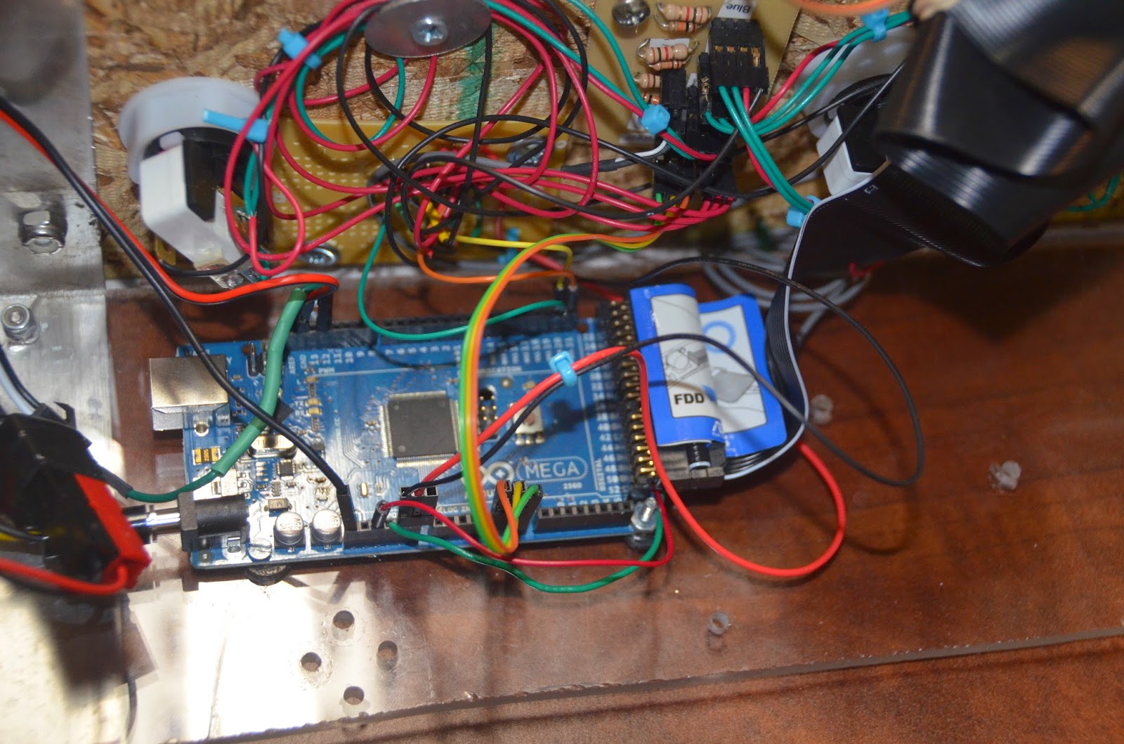
A second circuit board was hacked together when I realized that the 5V outputs from the Arduino Mega could not satisfactorily drive the LED lamps in the pushbuttons.  The outputs of this board go into the inputs for the LEDs of the previous board.  I used this webpage as a tutorial:  http://itp.nyu.edu/physcomp/labs/motors-and-transistors/using-a-transistor-to-control-high-current-loads-with-an-arduino/  .


 A couple of these LEDs seem to be systematically burning out, and I'm not sure if this is because of poor resistor selection or so other reason.  This is frustrating.  A ribbon cable was used to move pins 21 - 52 up near the LEDs, then jumper wires were used to make the connections between the ribbon cable and female headers soldered onto the LED PCB board.


For reference, here is a pinout table for the Arduino.

Green
Red
Yellow
50
30
26
45
32
28
44
33
24
46
36
BURNED OUT
43
35
23
41
34
27
48
39
25
49
37
29
47
38
31


Mega Wiring Diagram:
21… Red Transistor Board Wire
20… Yellow Transistor Board Wire
19… Green Transistor Board Wire

12… RGB Led Strip Control
GND (by #13):  Reset Switch
Reset:  Reset Switch
5V:  to Grey Cable (power to pullup resistors board)
GND:  to Grey Cable (ground to pullup resistors board)
A5:  Orange Buttons Wire
A6:  Yellow Buttons Wire
A7:  Green Buttons Wire


Tuesday, August 12, 2014

Rampant Robots at SAAS Middle School Robotics Camp

Three of my robots made appearance on the third day of a week long robotics camp for middle schoolers.  Most of the students were incoming 6th graders.  We did programming on the Lego NXT platform using the Enchanting program based on the LeJos firmware (Java).  On Wednesday, we took a break in the afternoon to watch a Discovery video discussing the future of robotics, and then the students were able to play with the Explorer Bot, Squirt Gun Tank, and the Frostruder.  I documented some of their interactions with the robots in pictures and videos.

Squirt Gun Tank:


Explorer Bot:


Frostruder:


Calculator Update

A student at my school spent some time last year updating the calculator code and also making a wonderful box for it.  Pictures of the box are below.


The code is posted on github:  https://github.com/gcronin/calculator/blob/master/mod/mod.ino .

Haven't had a chance to take much of a look at it, but very impressed by the young man who worked on the box and the code.  He has a bright future!!!!

Sunday, May 25, 2014

GPS Lockbox is Finished


 I finished putting together and testing the GPS Lockbox and it's working great.  Assembly was pretty straightforward once I got the staples box.   On the top of the box, I lasered out mounting holes for the LEDs, the keypad, and the LCD.  I mounted everything using #2.5 screws and some locktite.


 Two holes on one wall are used to hold the 5AA battery holder (which was hacked from a 9AA battery holder), and two holes on the adjacent wall hold the I2C GPIO board.  The 5AA batteries provide enough voltage to drive the Arduino Micro (specs recommend a minimum of 7V).  They also work out great to power the servo (typically servos run on 5-6V max), since that power is switched on and off by an NPN transistor across which there is a voltage drop of about 1.5V (2 diodes at 0.7V each).  With fresh batteries, 5 x 1.5V = 7.5V, so the servo sees about 6V.


I used very thin aluminum sheet between screws to hold the LEDs in place.   I epoxied the GPS on the top inside of the box after testing to make sure it could get a signal through the thin plywood.  That was no problem at all.


The servo was mounted using the same laser cut setup as I used for the keypad lockbox.  I reinforced the actuator, using a thicker catch meant for a quarter scale servo.

  I made a mistake when I glued the servo catch bracket to the inside of the top of the box.  As the box lid swung down, the catch hit the bottom of the box.  To fix this problem as neatly as possible, I lasered carefully into the bottom edge of the box, as shown above.  This actually had to be done from the top of the edge, which was done in several passes adjusting the focus to cut deep enough to remove a section of the wall.


Holes on the bottom hold the custom PCB board in place.   I made sure to label all the male headers soldered to the board.  I also installed a lighted power switch and even a jumper to switch main power to the servo from +5V from the Arduino Micro to Vin (directly from the 5AA batteries).


Finally, I mounted a USB Micro to USB plug, allowing me to connect to the microprocessor even if the box were locked.  The cut isn't very nice because it was done with a dremel.


The code went through minor revisions.  One of the "features" added is that the microprocessor now calculates the distance to the target automatically and scales the LED color between blue and red as the user gets closer to the destination.  This required a little trickery to get the microprocessor to wait for this distance calculation until it was receiving a valid latitude and longitude.  But that was pretty easy since the values from the GPS are zero until it has synced up.

Another feature that was added is that the "B" button now scrolls the user through the display being latitude/longitude, OR time, OR distance to target.  The "C" button will lock or unlock the lockbox, which is kind of cheating, but also nice in case it is not working or the user wants to end the game.

Finally, I got the RGB LEDs working in a way which was more helpful.  Some weird black magic is preventing logical transitions between green and red (eg yellows don't work).  They work fine when outside the rest of the code, but not inside.  As an example, the code at left generates red, green and blue values to fade the LEDs from red to green to blue and back to red.   The graph below (generated from Serial data from the Arduino) shows that the values are exactly what I want.
 In practice, what we see is a fade from green to blue to red, then a snap to green.  Very annoying.  Maybe it has something to do with the PWM output in some cases.  Rather than dealing with this problem, I bypassed it by sticking with green and red colors in the setup, then using a fast fade between colors when the box first starts up, and when the target location is found.  By making the fade fast enough, you don't really notice the snap from red to green.

"Finished" code is located here:  https://github.com/gcronin/GPSLockbox/blob/654401c2bf7ec7e60a410b5dd1b53714a5bf7f1f/GPS_distance/GPS_distance.ino  Ugly ugly code (as in hard for someone to understand and has lots of redundant code), but still very effective code (works great)!

PCB board files are linked here (use the ones called micro_board) and pictures of the Eagle schematics are shown below:


Next step; give the box to people for user testing!


Tuesday, April 29, 2014

Blistex Linear Actuator

Update:  5/19

I ordered a servo rotary driver from Servo City (part # SR500) which is a better way of coupling the leadscrew to the servo hub.  With a bit of modification, I was able to attach the leadscrew in a very permanent manner.  After reassembling and a slight modification to the location of the "in" magnetic sensor, the linear actuator is working great.

In the following video, I manually start the servo moving in or out, but it automatically stops at the limits (you can see the limit sensor values change from 1 to 0).  Near the end, I demonstrate that you can also use S to stop the actuator at locations other than the endpoints.  The code is the same as before.


Original Post

This project has been on my "to-do" list for quite a while.  All credit to the Matt Peick:  http://makezine.com/projects/make-34/the-mighty-lip-balm-linear-actuator/ .   Although it's a pretty simple build, I've had problems getting the lip balm "leadscrew" to attach to the servo shaft.  I've tried several kinds of glue (JB Weld*, Bond 527 cement) and tried to get a screw between the two of them but the leadscrew diameter is too small.  As a result, the linear actuator can push out fine, but the leadscrew pops off the servo as the linear actuator pulls in.  You can see this in the video below where the sound of the servo changes noticeable when the leadscrew comes off and the servo is now free-spinning.


I've ordered a couple items from ServoCity and I'm hoping one of these will allow me to make a better connection.  But for now, my implementation of this idea is not ready for usage.

Custom code for this item is on Github:  it allows in and out motion to be triggered using a serial window and also gives a bit of troubleshooting data (the sensor values and the servo pulse width).  https://github.com/gcronin/GPSLockbox/blob/master/blisterservo/blisterservo.ino

*Note: JB Weld is surprisingly poor at holding together plastics, especially smooth ones!


GPS Lockbox: Code Done, Assembly Begun

Last time I posted about the "guts" of a lockbox which would open when a certain location was reached.  The user would input a destination, start the program, the box would lock, and would not open again until the user were close enough to the destination.

I had worked out the details of reading the GPS, using the keypad through a GPIO I2C board, using a 8x2 LCD, and using some RGB lights as indicators.  Since that point, I have upgraded to a 16x2 LCD, and greatly upgraded the code, which now asks for user input (a destination location), calculates the distance to the location, modifies the RGB lights to have a color proportional to the distance to target (from blue == far away to red == close), and "unlocks" the box when close enough.

Original prototype for a 16x2 breakout board
for a Sparkfun LCD.  This is the one I am using
for the GPS lockbox.
The first modification was to use a 16x2 LCD from Sparkfun.  Data sheet is here.   It is SO much bigger than the 8x2, and it operates in 4bit mode meaning that only four of the eight data lines (DB0 - DB7) are needed to "run" the LCD.  I made a PCB breakout board for this one:  the Eagle data files can be found here. This process also opened up four more pins on the Arduino Micro... Enable, R/W, DB4, DB5, DB6, and DB7 are running to the analog inputs, freeing up four of the digital pins.

For the newer prototypes, the potentiometer
is underneath the LCD to minimize space.

I had previously had some confusion about the differences between different ways to represent GPS data.  I have standardized the code such that it always represents data in the format dd mm.mmmm.  This happens both when data is printed back to the computer over the serial port, and also when data is printed on the LCD.  This format can also be found easily online in many places like GPS Visualizer (see the picture below).  So this should make the process of inputting a destination pretty easy.

Next I added in code which allows the user to put in the target destination.  The most current version of the code is on GitHub.     The flowchart below shows the way that the keypad is read.  This is important, because it takes about a second to read the GPS and we only want this to be happening when the user is not entering data.  Otherwise the delay is impossibly confusing.  In addition, the flowchart always allows us to "start over" at any point by pressing A, so that we can always enter a new destination without having to restart the microprocessor.

The right hand side of the code is very similar to what I had in the first iteration.  The biggest change is that I realized that I needed to look for the $GPGGA ANYWHERE in the GPS string and not just at the beginning of the string.  I had thought my previous code did this, but I was wrong.  The line below looks for $GPGGA and also looks for an astericks after $GPGGA.  Since $GPGGA is at the start of the string and * indicates the checksum, the Parse flag is only set if a full string has been seen.

 if(StringContains(buffer, "$GPGGA")!= -1 && StringContains(buffer, "*") > StringContains(buffer, "$GPGGA")) {
        startPosition = StringContains(buffer, "$GPGGA") +7;
        Parse = true;
      }

The distance function on the right side is one that I just pulled directly from the internet.  I have no idea how it works; has to do with finding the distance along a great circle between the current location and the destination location.

The rest of the code is straightforward although the implementation is pretty course.  The Setup Program drops the Latitude Setup Flag, prints a prompt on the LCD for the operator ("Latitude: ddmmmmmm"), zeros the input buffer, and turns the LEDs red to show that we are waiting for input.

The Latitude Setup Program reads in the latitude as it is typed (slowly shifting the LEDs towards green) and prints the inputs on the LCD so that they replace the ddmmmmmm.  It takes 8 digits, then prompts the user to "Hit D".  Hitting D raises the Latitude Setup Flag, drops the Longitude Setup Flag, prints a prompt on the LCD for the operator ("Longitude: dddmmmmmm"), turns the LEDs red, and zeros the input buffer.  The Longitude Setup Program does the same thing as the Latitude Setup Program, raising the Setup Flag at the end.

The structure of the program allows the user to type A at any time which will lower the Setup Flag (bypassing GPS readings until the flag is set again) and allowing the setup program to run again in its entirety.

The last piece of this puzzle has to do with the RGB LEDs.  Originally I had hoped to have them fade throughout the program with the rate of fading increasing as the user got closer to the target destination.  While I updated the function fadeColor to be asynchronous (so the colors would change as the main loop cycled without a separate loop within the function), I found that the fade rate was limited by the loop cycle time, which was relatively slow because of the time required to read the GPS.  Fades either go impossibly slow OR huge jumps in color must be done each loop, which looks stupid.  So I will only use the fading at the very end as a sort of celebration once the box is opened.  Otherwise, once setup is done, the color of the LEDs is just set on a scale between RED (255, 0, 0) or BLUE (0, 0, 255) using a scale factor (eventually i'll program in the user to enter the approximate distance to the target and that will be the scale factor).  The variable "precision" is a threshold for how close the user needs to be to the target before the box opens.


I am working on putting all the components into a hinged box bought from Staples, product #942401.  Fortunately it laser prints beautifully.  I will have to figure out how the box physically locks.