This post is a bit dated and included for posterity. Back in the "day", the First Tech Challenge utilized a NXT microcontroller for a brain. It had a limited array of sensors which included those sold by Lego and Hitechnic. The latter were add-ons supported by NXT-G and with a series of libraries by a guy named Xander.
Around that time, IMU (inertial measurement units) came on the market, probably driven by their usage in cell phones to determine orientation. On a cell phone, this measurement allowed the phone to display landscape or portrait versions of a photo if the camera was flipped.
In a robotics club that I work with, I initiated some R&D to see if we could attach an IMU to the NXT. This initially was done by looking at integrating the allowed sensors (a gyro and accelerometer from HiTechnic), then by fooling with a disallowed Dexter IMU for the NXT, and finally to attempts to connect a Arduino clone to an NXT in order to use the huge array of available sensors for the Arduino platform.
In retrospect, this was not a successful project from the point of view of aiding the team, but I was able to hook up several sensors including a 9DOF Razor IMU and several Maxbotics Distance Sensors to an NXT via an Atmega chip.
Section 1: Testing Sensors Connected Directly to the NXT
Part A: IMU Quaternion Description
Robot motion in autonomous mostly consists of moving in straight lines, and turning. Encoders can be used to move in straight lines to a known distance, but making a robot move in a straight line can be challenging because of minor mechanical differences between two sides. Turning a robot a known amount is also very important, and best done using a gyro sensor. Gyro sensors are prone to drift though, meaning that even a non-turning robot may register a turn if the gyro rate of change is integrated over time.
Both of these problems would be solvable if we knew the orientation of a robot in space relative to the coordinate system of the playing field. The technology to find this orientation is well known as it is used in every iPhone or similar device. For a demonstration of the usage of an iPhone to move a robot, check out this post:
http://rampantrobots.blogspot.com/2013/04/turret-gun-iphone-control.html.
 |
| Figure 1 |
The technology involves a IMU, which is a device which contains a 3-axis gyro, a 3-axis accelerometer, and a 3-axis magnetometer. The gyro (Figure 1) measures rate of change about three orthogonal axes.
 |
| Figure 2 |
The accelerometer (Figure 2) measures the linear acceleration along those same three axes.
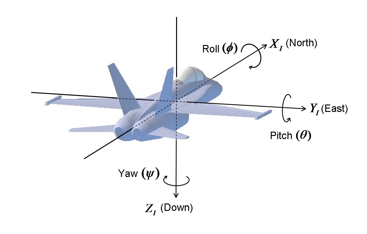
The magnetometer (basically a compass) measures the gravitational field along the same three axes. Advanced mathematics centered around linear algebra and vector calculus allows us to aggregate the 9 sensor values from the IMU and generate a very accurate representation of the orientation of the sensor in space typically relative to the Earth frame. The orientation of the IMU in space is typically specified by three Euler angles (Figure 3), which completely describe the relationship between a frame in which the IMU resides, and the Earth frame. Google “euler angles” for more information.
 |
| Figure 3 |
Integrating all three sensors can seem overwhelming, so there are alternatives which might be “good enough”. The first alternative is to remove the magnetometer, hoping that the gravitational field will not change dramatically. This leads to an integrated gyro/accelerometer. One implementation of the coding for this type of sensor is described in this
epic/awesome paper. I love the paper because it presents both the theory, and also a practical implementation of code written in C.
Part B: Dexter IMU
I ported this code directly to RobotC and started testing it using a nice 6 DOF sensor from Dexter Industries:
http://www.dexterindustries.com/dIMU.html. It’s built for use with the NXT and aggregates all 6 data points over one i2C bus. When playing with the code initially, I was surprised and happy to see that the newer versions of RobotC have much better support for math, including the atan2 function which was not present last year.
The code for the test with the Dexter IMU
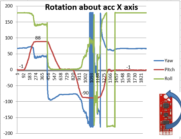
can be found on GitHub. An initial test was done with the Dexter IMU wherein the euler angles were printed to the DebugStream as the sensor was rotated in two orthogonal directions. The results of this test are shown in the graph in Figure 4.
 |
| Figure 4 |
We can see that Phi (φ) spikes as the sensor is rotated first in one direction, then back in the opposite direction all about one axis. Shortly afterwards, we see Psi (ψ) spike as the sensor is rotated about an orthogonal direction, then back. Interestingly, during the first rotation only Phi changes, but during the second orientation all three Euler angles change, although Psi changes most dramatically.
The code shown in the paper assumes a level of gyro drift over time. The amount of drift can be tweaked by playing with the value of the variable “gyroMeasError”.
Part C: HiTechnic Sensors
The Dexter IMU results looked promising, BUT this sensor was not approved for FTC usage unless it was run through the protoboard. The protoboard only has digital and analog I/O, and making i2C talk to these inputs was not worth the effort. However, we had the HiTechnic Gyro and Accelerometer sensors, so my next idea was to put them both on an NXT and modify the code to take data from these two sensors. The Gyro sensor only measures rotation about one axis, but I figured we were most interested in rotation about the axis perpendicular to the plane of the playing field, Psi (ψ). I assumed that rotation about the two orthogonal directions was zero ( this would always be true unless the robot tipped over or unless we were on the ramp). I manually set the code to have those two gyro values equal to zero.
Doing a quick test showed that the first Euler angle (called euler[0] in the code) appeared to be changing while the other two were remaining somewhat the same. A student helped me out here by suggesting that I display the values of the Euler angles right on the NXT screen so I could read them in real-time. This showed me that there was some drift going on with the first Euler angle. I modified the “gyroMeasError” until the drift seemed to be pretty small when considering a 1 minute window (as that’s about all we’d care about for autonomous). Once that drift was corrected, the results looked promising. So it was time to make a jig.
 |
| Figure 5 |
Calibrating a sensor like this really deserved the manufacture of a jig to automate the rotation of the sensors, and also to allow for linear motion. I constructed a rotating platform for the NXT (which had the sensors mounted directly on it) using a servo to rotate a lazy susan.
 |
| Figure 6 |
 |
| Figure 7 |
 |
| Figure 8 |
I calibrated servo rotation by setting the servo to sweep through a range of values in the code (100 to 200,
see the test program on GitHub. Then I took a video of the servo doing this motion from above. I used Powerpoint to figure out the exact starting and ending angles of the NXT. As show in the picture Figure 8, the NXT moved through an angle of 209 degrees corresponding to a servo change of 100 units in the code. This is more than is typical for a servo because the lazy susan is geared with a 1:3 ratio.
The last test I ran myself was to move the servo through it’s paces (from 0 to 209 degrees or 100 to 200 servo code units), and measure the Euler angles.
The code is on github.
The raw data didn’t look great, but when I converted the first Euler angle to degrees (multiplying by 180/Pi) and converted the code servo angle to actual angle (using the linear mapping function angle = [209/100] * code_servo_units – 209 ), I found that there was a pretty good match between the Euler angle and the real angle as shown in the graph in Figure 9.
 |
| Figure 9 |
I ran it again, this time introducing a delay between servo steps. The raw data graph shows the delay as stair-steps in the red line. The processed data again shows a good match between the actual and the sensor calculated angle (Figure 10).
 |
| Figure 10 |
The last test that I did was to have the servo hold a position for 10 seconds, and look at the drift of the first Euler angle (Figure 11). You can see that there is a start up period of about 2 seconds where there is little correlation between the real angle and the sensor angle (Figure 12). I know that about 2 seconds had past because there were about 85 iterations of the while loop which occurred, each taking about 0.023 seconds (the loop time was written to the debugStream). After that, the sensor angle approaches zero (which is the position of the servo since it was held at its starting position throughout the test). The variation in sensor value over the last eight seconds of the test is less than half a degree.
 |
| Figure 11 |
 |
| Figure 12 |
Part D: Assessing the Accuracy of the HiTechnic Sensor Algorithm
 |
| Figure 12 |
At this point a student and I tested linear motion as the servo was moving through an angle to see what the effect of changing accelerometer readings would be on the algorithm. Figure 12 shows the servo being held at a position (red line) and the calculated angle (blue line). Although they don’t match exactly, they are within five degrees with the Actual Angle being 0, and the calculated angle being 359. The test duration was a little over 10 seconds.
 |
| Figure 13 |
Figure 13 shows the servo being held at position 100, while the NXT and sensors were slid linearly along the drawer slide. There is slightly more discrepancy between the actual and theoretical, with the actual moving from 2 to 0 degrees, while the calculated started at 355 and moved down slightly to 348, a difference of 12 degrees at worst. Based on only this test it is hard to make any conclusions, but it does look like linear motion is having an adverse affect on the algorithm.
I moved to streamline the process of getting the real and calculated angle as well as the difference directly from the debug stream. The results were not great since I was seeing a) a discrepancy between real and calculated, and b) the discrepancy was not predictable. Figure 14a shows a test done on 10/9/13 (see the
Git commit on that day for code). There is a somewhat constant difference of 8-10 degrees with the calculated angle always lower than the actual angle. Figure 14b was the same code tested the next day (10/10), and unfortunately the results of the previous day are not exactly repeated. The Euler angle still falls below the actual angle, but now the difference is more of a function of servo position, and the difference is also larger than on the previous day. Figure 14c is a third test also done on 10/10, now with a third graph which shows the difference (the green curve). We can see it is even larger than in either of the previous two graphs, being around 20 degrees now.
 |
| Figure 14 |
These results were pretty disheartening, since differences which are that big and that unpredictable would either make this algorithm useless, or require a complex calibration to be done at the beginning of a program to read the difference and compensate for it.
When I work with students, I often tell them to look at the raw data when they are processing it and things are not going well. On 10/16, I ran tests to record the raw values from the gyro and the accelerometer. I did this partially to see if there were patterns as well as to measure the gyro drift. The quaternion algorithm I am using requires one to input the magnitude of the gyro drift, and I figured getting the real value rather than guessing might be a good idea. I had previously set the drift such that the calculated angle was constant over a 30 second interval. The gyro data (Figure 15) oscillates around zero with some spikes. The most common positive value is 0.26 deg/s, and the most common negative value is -0.74 deg/s. The spikes go up to about 1.26 deg/s. The average gyro drift over the period of this test was 0.06 deg/s.
 |
| Figure 15 |
On 10/16, I ran a series of tests changing the value of the gyro error factor. All tests were run by setting the servo angle to 0, 52, 104, and 157 degrees and recording the calculated angle and the difference between the actual servo angle and the calculated angle. Figure 16 summarizes the results. Large negative errors didn't work, and small negative errors led to substantial drift over time. The calculated average value of the gyro drift did not outperform any other positive numbers. Larger positive numbers seemed to minimize drift over time, but they also led to a much longer “start up time”. With an error value of 1 deg/s, the initial convergence was much faster than with the error set to 30 deg/s.
 |
| Figure 16 |
Section 2: An Atmega/NXT Interface
A: FTC Rules and Constraints
All of the testing described in Section 1 suggested to me that it was going to be hard to get good results for an IMU based on allowed NXT based sensors.
Per the rules from the 2013-14 game,
“Only LEGO Approved NXT and RCX sensors (as indicated by the LEGO certified hardware label), and HiTechnic NXT compatible sensors are allowed to be directly connected to the NXT, the HiTechnic Sensor Multiplexor, and the HiTechnic Touch Sensor Multiplexor.”
“HiTechnic SuperPro Prototype Board, and the NXT Prototype Boards (both solderable and solderless) are allowed with the following constraints:
i. All power used in the circuits connected to the Prototype Board must be derived from the power connections provided within the board. No batteries or external power sources are allowed.
ii. Circuits may connect only to the named connections provided by the Prototype Board (i.e. A4-A0, B5-B0, 3V, 4V, 9V, 5V, GND) or SuperPro Protype Board (i.e., A3-A0, B7-B0, S3-S0, O1-O0, WR, RD, 3V, 9V, 5V, GND)
iii. Communication to the NXT Controller may only occur through the included NXT connector.
iv. Any compatible sensor may be connected to the Prototype Board, provided that no other rules are violated. Sensors may be distributed throughout the Robot; they do not need to be physically attached to the Prototype Board.
v. Additional circuit boards may be connected to the Prototype Board as needed.
vi. The processor included in the Prototype Board may not be reprogrammed.
vii. Circuits included as part of the HiTechnic Prototype Board may not cause interference with any Robot on the playing field, any part of the field management system or any game element.
viii. Non-LEGO certified sensors may only be attached to an NXT Prototype Sensor Board or a SuperPro Prototype Board.”
B: Atmega 168 or 328/Protoboard Interface
In short terms, the rules meant that we were stuck with Lego/Hitechnic products attached directly to the NXT, but could use pretty much any sensor as long as it was run completely through the protoboard without modifying the protoboard. The specs from the protoboard suggested that the power limitations on the protoboard are pretty severe:
see this link. Specifically, the specs show that the 3.3V pin can supply 15mA while the 5V and 9V pins can supply 8mA. In communicating with the
Nannites, team 4092 from Portland OR, I learned that you can in fact use the 3V power pin to supply 200-400 mA of current. They used this in the past 2012-13 season to develop an IMU sensor using gyro/accelerometer and multiple compass sensors which gave them positional accuracy within a degree.
Working with another mentor, I tried to power an Arduino using the 5V and 9V pins on the protoboard, but nothing happened. Separately, we tested the current draw from the Arduino and found it to be roughly 50mA. The Arduino Uno requires a power supply exceeding 5V input. However, the Atmega chip itself can run on lower voltages (1.8 – 5.5V per the specs,
located here)
We ordered some Atmega 168 chips from Digikey (ATMEGA168A-PU-ND, $3). These are similar to the chips that the Arduino Uno uses, but without all the “infrastructure” around the chip (incidentally, the Uno costs about $30, or ten times the cost of the chip!). The Atmega 168 is programmable using an ISP programmer. Tim and I worked from the clear directions in the book
Make: AVR Programming by Eliot Williams. We were able to download a simple LED blink program onto the chip and tested it out using the power from 3.3V pin on the protoboard. It worked! The current draw was about 1.5mA without the LED (just for the chip).
Next Tim and I worked to establish a communication protocol between the Arduino and the NXT. The basic idea is to use 9 of the digital output lines from the Atmega 168 to represent bits in a 9 bit number. By setting each of the lines either high or low, you can use the Arduino to represent any number between 0 and 511 (2^9 - 1). I used pins D0 – D8 as the 9 output lines from the Atmega168. Those are routed to the five analog ins from the protoboard (D0 -> A0, D1 -> A1, etc) and then to four of the six digital IO for the protoboard (D5 -> B0, D6 -> B1, etc), as shown in Figure 17.
 |
| Figure 17 |
A simple test program was written to show that the NXT could “see” highs and lows set to both its analog and digital pins.
See the code on Github. This worked great; I could see either 1023 or 0 for the analog inputs (high or low output from the Arduino), and a hexadecimal representing the digital inputs on the NXT of either x00, x01, x02, x04, or x08, corresponding to 0000, 0001, 0010, 0100, or 1000.
I played around with sending a specific value OUT from the Arduino, and reading that same value IN on the NXT. I wanted to be able to see the “raw” output from the Arduino and the raw input from the NXT at the same time. I used LEDs connected to the output pins on the Arduino to visualize which pins were high and which were low. I used the LCD display on the NXT for the raw incoming data.
I wrote a program which generated a random number on the Arduino, then masked and bit-shifted the number to separate it into 9 bits. D0 represents the 2^8 place (the highest value bit). D8 represents the 2^0 place (lowest value bit). The program turns on or off bits to represent the random number in binary. On the NXT side, the NXT does the math in reverse to regenerate the number.
On the Arduino:
for (int dPin = 0; dPin < 9; dPin++)
{
int value = randNumber&(1<<dPin); //mask the number in the dPin bit position
value = value >> dPin; //shift back so that
digitalWrite((8-dPin), value);
}
Example: Suppose value is 446 = b110111110. The values for each Arduino pin are calculated as shown in the table below.
On the NXT:
value = 0;
for(int i=0; i<5; i++)
{
_chVal = HTPBreadADC(HTPB, i, 10); //Read an Analog Pin
switch(i) {
case 0: //A0
if(_chVal>512) value+=(1<<8);
break;
case 1: //A1
if(_chVal>512) value+=(1<<7);
break;
case 2: //A2
if(_chVal>512) value+=(1<<6);
break;
case 3: //A3
if(_chVal>512) value+=(1<<5);
break;
case 4: //A4
if(_chVal>512) value+=(1<<4);
break; }
}
inputs = HTPBreadIO(HTPB, 0x3F);
value+=(inputs&0x01)<<3;
value+=(inputs&0x02)<<1;
value+=(inputs&0x04)>>1;
value+=(inputs&0x08)>>3;
Example: Continuing our example from above (value is 446 = b110111110), the table below shows how the NXT code reconstructs the value 446.
Figure 18 - 20 show that this methodology works. The right hand side of each picture shows what is coming out of the Arduino. The NXT LCD shows what the NXT sees. The LED “bit pattern” and the NXT received numbers match up.
 |
| Figure 18 |
 |
| Figure 19 |
 |
| Figure 20 |
As a fun aside, I modified the program to just print sequential numbers. This provided an easy way to visualize binary counting as the LEDs show us the bit sequences. Click on Figure 21 to go to the video.
C: Adding in a Razor 9DOF IMU
With a way to pass data between an Atmega chip and the NXT, the next step was to connect up a commercially available IMU to the Atmega, read its orientation, and pass this to the NXT. I used the Razor Sensor Stick 9DOF IMU as well as adding in a touch sensor on the NXT to signal the Atmega to send a value to the NXT when desired.
I attaching B4 from the Protoboard to D2 on the Arduino. Pins 2/3 on the Atmega 168 have hardware interrupts. I rerouted pin B2 to D9 on the Arduino. The new wiring diagram is shown in Figure 22.
 |
| Figure 22 |
With this is place, I modified the code slightly so that the Arduino code generated a new random number only when the interrupt pin saw a rising voltage. This worked fine, although I had to tweak the output pins as follows.
for (int dPin = 0; dPin < 9; dPin++) {
int value = randNumber&(1<<dPin);
value = value >> dPin;
if(dPin != 6) digitalWrite((8-dPin), value);
else digitalWrite(9, value); }
This works by just skipping the 2nd pin (which is now an interrupt) and replacing it with the 9th pin. Note that the 2nd pin is when dPin = 6 because we are writing to pin 8 – dPin. There were also a couple code cleanups on the NXT side. I was originally setting all the digital I/O as outputs, but actually only B4 should be an output. This didn’t seem to mess up anything before, but now I was going to write to one of the outputs so I wanted to make sure the others were set as inputs since you write to all the pins using one byte.
// Setup all the digital IO ports as outputs (0x10) 010000 pin B4 = output, others // are inputs.
if (!HTPBsetupIO(HTPB, 0x10))
Also, this is how I wrote to just pin B4. This works because hex 10 is 010000
if(touchValue == 1) { HTPBwriteIO(HTPB, 0x10); } // turn on B4
Now whenever I pressed the touch sensor, I got a new random number from the Arduino.
The full code is here.
Next I started playing with the
9DOF Sensor Stick. The tutorial on the Sparkfun website was what I worked off of:
https://github.com/ptrbrtz/razor-9dof-ahrs/wiki/Tutorial. The manufacturers of this sensor have written firmware for the Arduino which uses a quaternion approach to calculate the three Euler angles based on the values provided from an accelerometer, gyroscope, and magnetometer on the sensor stick.
I downloaded and tweaked the sample code on that site and was able to see values of yaw, pitch and roll as the sensor was moved when hooked up to an Arduino UNO. When I tried to compile the same code for the Atmega 168 (3.3V 8Mhz), the code was too big. The RAM limitation for this chip is about 14000 kB. I commented out all of the “output.ino” file which was for serial communications. I turned off all serial communications. I pruned down the main loop, cutting out all but the timestamp check to only read new data every 20ms. I changed the interrupt function so it just raised a flag “writeToNXT”. In the main loop, if this flag is true the Arduino sends the “yaw” value, Psi (ψ), to the NXT as a 9bit number.
The relevant commit is here. Look at the file Razor_AHRS.ino (the original has been renamed OLDRazor_AHRS.ino). I also made sure that the 9DOF could run off 3.3V, and it seems to run fine. An updated wiring diagram with the 9DOF is shown in Figure 23.
 |
| Figure 23 |
After figuring out that I had to send the yaw in degrees (not radians-hence line 304), I was able to see a changing value on the NXT. Since the angles between sent could be negative but my algorithm didn't allow for negative numbers, I mapped the yaw value from -180..180 to 0..512 in the Arduino software...
sendNXTdata(map(TO_DEG(roll), -180, 180, 0, 512));
...and then mapped back in RobotC...
int mapNineBitToDegrees(int nineBitNum)
{
float Degrees = 0;
float NineBitNum = 0;
float slope = 360.0/512.0;
NineBitNum = (float)(nineBitNum);
Degrees=slope*NineBitNum;
Degrees=Degrees - 180.0;
return (int)(Degrees);
}
I did a few quick tests to see what sort of yaw I was getting. When running the 9DOF sensor stick directly from an Uno, I could see that i just needed to spin the sensor about it’s flat axes to see the yaw changing. I didn’t really calibrate other than doing this. So I recorded the values from the NXT as a function of real world angle. The yaw values kept changing for about 10 seconds after the move was done before stabilizing. There was a trend at least for the first three measurements, but the last one was very weird and a bit disconcerting as shown in Figure 24.
 |
| Figure 24 |
Without being able to see the values being sent from the Atmega 168 directly (because I had turned off the serial communications functionality), I found myself in the dark about whether the values being read by the NXT were actually "good". This necessitated a shift to the Atmega 328 (which has a larger maximum size for sketches). I also had not done any calibration of the 9DOF sensor stick.
D: Preliminary Calibrations of 9DOF Razor
 |
| Figure 25 |
I manufactured (laser printed) a small cube within which I mounted an Arduino and the sensor stick. I made sure to carry the orientation markings of the three sensors onto the outside of the box for ease of calibration. The sensor and microprocessor were also securely mounted which prevented unwanted motion during the calibration process.
I followed the calibration process directions to the best of my abilities.
Directions are posted here. It was fairly painless, although moving the sensor very slowly during the accelerometer portion of the calibration is tough to do patiently. The values recorded for the accelerometer are shown below:
#define ACCEL_X_MIN ((float) -275)
#define ACCEL_X_MAX ((float) 261)
#define ACCEL_Y_MIN ((float) -246)
#define ACCEL_Y_MAX ((float) 256)
#define ACCEL_Z_MIN ((float) -280)
#define ACCEL_Z_MAX ((float) 251)
Per the instructions, I skipped over the magnetometer calibration and onto the gyro calibration. That one was easy because you just let the sensor sit while the program integrates error. The values recorded for the gyro are shown below:
#define GYRO_AVERAGE_OFFSET_X ((float) 2.42)
#define GYRO_AVERAGE_OFFSET_Y ((float) 52.42)
#define GYRO_AVERAGE_OFFSET_Z ((float) -17.76)
Finally, I downloaded the Processing sketch, installed the EJML per the directions in the Processing sketch, and ran the sketch. I had to change the baud rate to 38400 for my computer, and also change the COM port before it synced up to the Arduino. Getting the Processing sketch to “quit” by pressing space bar was a little finicky… the first time it wouldn’t recognize the space bar and told me I had too many data points. So I compromised and covered most of the sphere before pressing space bar a lot to get the program to quit. The values recorded for the magnetometer from processing were:
const float magn_ellipsoid_center[3] = {44.0805, 84.8388, 4.76567};
const float magn_ellipsoid_transform[3][3] = {{0.772262, -0.00760499, -0.0272766}, {-0.00760499, 0.926243, 0.0323994}, {-0.0272766, 0.0323994, 0.981637}};
After the calibration was done, I entered the values into the Razor_AHRS firmware code and recompiled onto the Arduino. I ran a series of simple tests where I rotated the cube in 90 degree increment, not super fast, every 5 seconds or so, until I had rotated four full turns and was back at the starting location. I pulled the yaw, pitch, and roll values from the Serial Window, entered them in Excel, and plotted the results.
This is a link to the Excel document used to generate the plots. The graphs are shown in Figures 26-28.
 |
| Figure 26 |
 |
| Figure 27 |
 |
| Figure 28 |
The ROLL values changed nicely and repeatedly. Unfortunately, this motion is not particularly helpful for a robot chassis (it's the motion equivalent to a car that is rolling down a hill).
E: A Printed Circuit Board (PCB) for Reliability and Testing
I used Eagle CAD to make a PCB board for a 28 pin Atmega chip (eg 168 or 328) to connect it to the NXT protoboard. The board has hookups for an FTDI (so the Atmega chip can send and receive serial data from a computer), an Arduino (to be used as an ISP), and an I2C sensor (such as the 9DOF Sensor Stick). Since the NXT <-> Arduino interface and the FTDI share pins D0 and D1, I used jumpers which allow you to switch the connections of those pins. Also, since the FTDI and Arduino ISP are usually 5V devices while the I2C sensor we are using is a 3.3V device, there is a power select jumper, and the sensor is only connected to 3.3V coming from the protoboard.
 |
| Figure 29 |
Figure 29 shows the schematic. It shows connections between items, but not the actual locations on the board.
 |
| Figure 30 |
 |
| Figure 31 |
Figure 30 is the layout. Green shows pads where components will be soldered. Blue lines are called traces and will be electrical connections between components. The Eagle CAD had too many lines and so I ended up having to route six wires across the top of the board. These are shown in the layout above as yellow lines.
 |
| Figure 32 |
Figure 31 shows the same pictures as above but with the actual components removed so it is easier to see the traces. In addition, you can see the tool path here; it is the very thin lines around the blue traces. The traces and pads are removed in Figure 32 to clearly show the full tool path. The tool path splits the copper into isolated areas.
 |
| Figure 33 |
Figure 33 shows the actual copper after it was milled. You can see that it is a mirror of Figure 28.
 |
| Figure 34 |
After milling, holes are drilled for the component pins as shown in Figure 34.
 |
| Figure 35 |
F: Protocols for Testing the Razor 9DOF with the PCB
I was really hoping for students to do the work on figuring out if the Razor 9DOF was a viable option for them. I setup a system which would make it relatively approachable. First, I switched to an Atmega328 because of the additional memory. To program the chip, I used a Arduino Duemilanove as an AVR ISP (In System Programmer); see his webpage for more details:
http://arduino.cc/en/Tutorial/ArduinoISP. Although you can upload a bootloader to an Atmega chip, which would allow you to program via FTDI, I wrecked a couple chips with failed boatloader uploads and became gun-shy of this technique. The ISP doesn't necessitate any changes to the chip. Figures 36 and 37 show the wiring for uploading a sketch.
 |
| Figure 36 |
 |
| Figure 37 |
NOTE: AT ANY TIME, EITHER THE DUEMILANOVE ISP OR THE HITECHNIC PROTOBOARD CAN POWER THIS SYSTEM. BOTH SHOULD NOT BE CONNECTED SIMULTANEOUSLY.
The following is the series of steps used to upload a sketch to the Atmega328:
- Open the Arduino IDE, click on Tools/Boards and select Arduino Dueminalove with ATmega328. Click on Tools/Serial and select the correct serial COM port for the Arduino board.
- Click on File/Examples/ArduinoISP to load a sketch which will allow the Dueminalove to be used as an ISP. Click on the upload button to compile and download this sketch onto the Arduino. Make sure that the red/green/and yellow LEDs on the custom board all flash once, then the green light should be a “heartbeat” pulsing once a second.
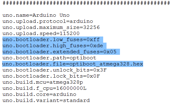
- You will need to add a new “board” with custom settings for the atmega328. Download the boards.txt file from here: https://sites.google.com/site/rampantrobots/nxt---arduino/boards.txt.
- Close the Arduino IDE, then navigate to Arduino 1.05/Hardware/Arduino folder. You will find a file “boards.txt” in that folder. Delete it, and replace with the file you just downloaded.
- In your Arduino folder, find the subfolder: ..\hardware\tools\avr\etc. Make a backup copy of the file: avrdude.conf
- Open the file avrdude.conf in a text editor
- Search for: “0x1e 0x95 0x0F” (this is the ATmega328P signature)
- Replace it with: “0x1e 0x95 0x14” (this is the ATmega328 signature)
- Save the file
- Open up the Arduino IDE again, go to Tools/Boards and you will see a new choice called NXT INTERFACE. Select this.
- Open the program you wish to upload in the Arduino IDE.
- HOLD DOWN SHIFT and press the UPLOAD arrow button. This process will use the Duemilanove as an ISP to put this blink sketch onto the Atmega328. If it works correctly, you should see the TX and RX lights on the Duemilanove rapidly flash. The red LED on the custom board may light up, but should unlight after the sketch is uploaded. At the bottom of the Arduino IDE, it should say Done Uploading. If there is any sort of red text error, try the SHIFT/UPLOAD button once more, then check with me to troubleshoot.
The video linked to Figure 38 shows a sketch successfully be uploaded to the Atmega328.
 |
| Figure 38 |
The first version of the firmware can be used with Processing to visualize the orientation of the Razor as shown in the video linked to Figure 39. The Processing sketch to use
is here. A static version
can be found here.
The second version of the firmware requires an additional program for the NXT, written in RobotC.
The code is located here. A demonstration is shown in the video linked to Figure 40. The 9DOF Razor is being rotated as shown in Figure 26.
G. Improved PCB with Simultaneous FTDI and NXT
I designed a better PCB board to connect an Atmega328 to a HiTechnic Protoboard. Increased functionality of this board includes simultaneous FTDI and NXT connections, 3v3 to 5V voltage conversion and vice versa, and space for the attachment of two analog (or digital) sensors in addition to the I2C connection.
The previous PCB board had a pinout which shared atmega328 pins 0 and 1 with both the FTDI and the Hitechnic protoboard. You could use either, but not both, and you chose which to use by setting two jumpers to either the NXT or FTDI position. In addition, testing with a multimeter showed that the 4V pin on the Hitechnic protoboard were actually running 5.3V, while the 3V pin on the protoboard was running at 3.67V. Hence when a pulse was sent from the Atmega328 to the protoboard, a high of 5.3V was going into a pin expecting to see a high of 3.67V. Not good electrical engineering design!
 |
| Figure 41 |
As part of the testing phase, I also tested the internal resistance of the Hitechnic Protoboard 4V supply. This was done by attaching a 1k potentiometer and a multimeter in series between the 4V and GND pins. The resistance of the pot was varied starting at 1k and slowly decreasing, measuring the voltage at the pin and the current supplied for each step. Voltage was plotted as a function of current, and the resistance was determined as the slope of a best fit line (since V = R I) as shown in Figure 41. The bad news is that the internal resistance is pretty high (8 ohms). The good news is that the supply can source up to 25mA of current without a problem.
To fix the FTDI/Protoboard problem, I just mapped new pins to the protoboard and left pins 0 and 1 available for the FTDI exclusively. The new pin mapping is shown in Figure 42:
 |
| Figure 42 |
To fix the voltage mismatches (any row where the 2nd and 4th columns do not match), I used voltage level converters. A 74LVC245 chip from Adafruit (
http://www.adafruit.com/products/735) provides voltage level shifts in one direction between 3v3 and 5V. I used it to convert down from 5V coming out of the atmega328 to 3v3 going into the Hitechnic protoboard on atmega328 pins 4-10 and A0 (14). I used a Sparkfun bidirectional logic level converter (
https://www.sparkfun.com/products/12009) for pins 2 and 3 (both being shifted UP from the Hitechnic 3v3 to the atmega328 VCC of 5V) as well as A1 (15) being shifted down from 5v to 3v3. Finally, I used a PCA9306 breakout board from Sparkfun (
https://www.sparkfun.com/products/11955) to deal with the voltage mismatch on the i2C pins (A4 and A5) going into the Sparkfun 9DOF Sensor Stick IMU.
 |
| Figure 43 |
I first laid out all the connections on a solderless protoboard, which made a huge mess as shown in Figure 43. After a bunch of troubleshooting, described in some detail in
this document, I was able to get the system up and working. A very important note is that the code for outputting a nine bit number from the Atmega328 had to be changed because of the new pin mapping. A1 and A0 respectively map the lowest bits (A1 is the lowest so no bitshifting, while A0 is bit shifted once). This coding is done manually. The rest (pins 4-10) is done in a
for loop.
void setupNXTpin()
{
for(int i=4; i<11; i++) {
pinMode(i, OUTPUT); }
pinMode(A0, OUTPUT);
pinMode(A1, OUTPUT);
//attachInterrupt(0, interruptFunction, RISING); // setup pin 2 as an interrupt
}
void sendNXTdata(int numberToSend)
{
int value = numberToSend&(1<<0);
value = value >> 0;
digitalWrite(A1, value);
value = numberToSend&(1<<1);
value = value >> 1;
digitalWrite(A0, value);
for (int dPin = 4; dPin < 11; dPin++)
{
int bitShift = dPin - 2;
int value = numberToSend&(1<<bitShift);
value = value >> bitShift;
digitalWrite((14-dPin), value);
}
}
The Razor firmware for the 9dof sensor stick with these functions integrated can be
found on GitHub here. I tested it and it works great; you can see the same values on both the NXT screen and also on the serial monitor in the Arduino IDE; see the video linked to Figure 44. I was not, however, able to get this PCB board to "sync" with Processing in the manner shown in Figure 39 for the previous PCB board.
 |
| Figure 44 |
 |
| Figure 45 |
I designed a PCB board for this setup. It’s a much more complicated board with the additional of the voltage converters and required a few electrical lines across the top of the board as shown in Figure 45. The Eagle files can be found here (they are the ones called NXTArduinoInterfacev3):
https://sites.google.com/site/rampantrobots/nxt---arduino.
 |
| Figure 46 |
The fabricated board is shown in Figures 46-48. Note that only one jumper remains; we still need to select whether the Atmega328 is powered by the ISP or the NXT. The jumper eliminates the possible problem of having both connected at the same time.
 |
| Figure 47 |
 |
| Figure 48 |
Section 3: Maxbotix Ultrasonic Distance Sensors
By the time the last version of the Atmega/Protoboard PCB was made, tested and debugged, that ship had essentially sailed. My efforts did not really support the student's work and they wanted less convoluted solutions. In addition, our lead programmers was having problems with the magnetometer getting messed up by the magnetic fields close to motors. So I switched to looking at the line of
Maxbotix Distance Sensors, several of which were around.
I designed and 3D printed a part which could hold several of these sensors as well as a Lego Ultrasonic Sensor.
The CAD file can be downloaded here.


