Sunday, January 27, 2013

Turret Gun: Stall Checks

Stall checks are a failsafe step which increases reliability and decreases maintenance.  When electrical motors are stopped but power is still applied the windings on the inside of the motor can heat up too much, leading to burnouts as the windings melt through insulation and begin shorting, or melt completely, increasing the resistance until the motor smokes.  The tetrix motors are particularly bad in this sense; they smoke whenever they get stuck.

A current sensor is probably the best option for preventing stalls.  The current sensor reads the current that the motor is drawing.  Motors have a rated stall current; if the current sensor reads this current, then power can be cut to the motors for some period of time before allowing the program to "try again".

Optical encoders provide another easy way to check for a stall; if power is applied to the motor, then the encoder reading should be changing over time.  If the reading is static then the motor is stalled and power should be cut.  The code and the algorithm shown here do exactly that.

The issue with a stall check is not really in detecting the stall, although you do have to be careful about how often you check, and how much the encoders must turn before you are satisfied that the motor has not stalled.  Instead, the issue is how you recover after you have stalled.  Once power is cut to the motor, it will not be able to spin, meaning the encoder values will not change.  If your only algorithm is the one shown above, then you will have to reset the program completely once any stall occurs.

Another related issue occurs when you want to apply power for the first time.  Before power is applied to the motor, the default for a current sensor algorithm will be "OK, you can power the motor", because the current is zero.  However, the default for an optical encoder algorithm will be "No, you can't power the motor" because the encoders aren't changing values.

To get around these problems, you need to work harder with encoders than you do with a current sensor.  You need to consider both a) is the motor stopped because no power is applied or because it is stalled, and b) is the motor stopped and ready to startup again.  Fixing a) is pretty easy by adding in the question of "is power applied?", and only running the stall check if it is.
The much tougher question is how to get the motor running again.  What I did was the following.  Consider that for the motor to begin again, we want the user to recognize a stall and remove power to the motor.  After this point we want the program to be allowed to attempt to run the motor again without implementing the stall check.  There should be a "grace period" where the motor gets a shot to start moving again, BUT the grace period can't be too long in case the motor is truly stalled.  So first we need an algorithm to recognize if the joystick has been returned to a zero position, indicating recognition of the stall.  One such algorithm is as follows.  We keep track of the last time the motor power was non-zero... if more than 200 ms have passed since the last non-zero motor power reading, we assume that the joystick is centered and we raise a "stopped flag".


Once that is all in place, we can put it together with the stall check algorithm as follows.  If the stopped flag is raised and the joystick is now in a nonzero orientation, we apply power to the motor for 300ms without running a stall check.  Once we've done this, the "stopped flag" is lowered and the stall check will be occurring again.


The only trick is the ordering.  The checks for the stop flag and for the current motor power need to happen first in the loop, followed by the stall check algorithm, and ending by resetting the timer.  This order allows for the stop flag to be raised at the same time that a non-zero power is applied, allowing us to enter the 300ms grace period where the stall check is not run.

The algorithm does add a level of latency due to the delay which stops the microprocessor while a motor is run.  But this was the best I could come up with at this point.

Thursday, January 24, 2013

Turret Squirt Gun: OSC iPad Control

Using a joystick is great for controlling many applications, but it requires that you have a laptop.  For this project, I thought it would be interesting to see if another control device could be used to run the squirt gun turret.  I found that Processing supports the OSC protocol, which sends packets over UDP (a protocol which runs over IP but without the error checking of TCP).  I used the TouchOSC application to create an interface on an iPad to run motors, the squirt gun, and the pan/tilt servos.  There is a library called oscP5 for Processing.

The TouchOSC interface is simple to use and completely customizable.  The interface I made is shown at left.    Every fader, button, or xyPad has an "address", shown on the left, and has customizable values.  For example, I setup the highlighted fader (which has the address /1/fader3) to have possible values between -100 and 100.  There is an app which you can download from the iStore for the iPad/iTouch/iPhone.  In the app, you set the IP address of the host computer.  Then you choose "sync" in the TouchOSC program, and the program sends your interface to the app on the iPad.  The iPad screens looks exactly like the interface you made in TouchOSC.

Once the iPad is setup with the IP address of the host computer, they can talk to  each other over any network as long as they are both on the web.  This means that as long as the computer is networked and is in the same location as the robot, the robot can be controlled from anyplace that the iPad can get an IP address.

The Processing code to read the OSC is shown below.  It basically parses the OSC packet to read the value of each fader, xygrid or button.    To download the code, click here.

I found that the communication protocol was not super robust.  For example, it worked with an iPad but not with an iTouch or an iPhone.  It worked very well with an iPad when the turret gun was connected to the host computer directly through an FTDI cable (see the video of the gun in action on this post).  However, behavior was erratic when the FTDI was replaced with Xbees... the gun, turret, and motors would randomly move or turn on when they were not commanded to.  This happened enough that I abandoned this interface and reverted to the joystick, which was much more reliable.  Nevertheless, for applications which are more tolerant of potential errors, this would be a fun system to use.

Wednesday, January 9, 2013

Turret Squirt Gun


I reached back to the Explorer Bot project here and tried to incorporate the squirt gun used for that project by mounting it on a working turret.  When the Explorer Bot project was going on, I found that AX12a servos did not have the torque required to manipulate the squirt gun.  For this project, I used RX64 servomotors also from Trossen Robotics.   The manual for these servos can be found here.  These are extremely high-end servos with huge torque capacities.  Unlike the AX12a's, there was little I could find online to show how to use these devices directly with the Arduino.  They use an RS485 serial protocol and a packet system.  There is programming support for the RX64's in the Arduino language, but the hardware connection could be bypassed by using a Arbotix microprocessor board.  It uses the same chip as the Arduino and can be programmed using the Arduino IDE.  It's a little more expensive that the Arduino, but it also has built is support for the AX12's (or the RX64's with the RX Bridge), a spot for Xbees, better headers for sensors, and support for optical encoders.  It uses an FTDI serial interface rather than USB as the Arduinos do.  I should stress that this is NOT plug and play for the RX64s or the AX12s.   It took me some significant troubleshooting to get the servos working.  The support network for the Arbotix is nowhere near as extensive as for the Arduino.  Frankly I've found Trossen's support to be inadequate, but maybe that's just cause I do not know what I'm doing yet!

To first put the board through its paces, I ran a series of tests, which are described in this document:  Arbotix I/O Testing Document.  These allowed me to test the digital and analog inputs to the board, to see if it could run pulsed servos, to see if it could run an HB-25 motor controller (datasheet), and to see if it could read optical encoders on motors.  I used the E4P optical encoders (datasheet) on Tetrix motors (datasheet) for my test platform.  

Everything worked pretty well almost the first time around.  The only troubleshooting that I had to do was for the HB-25 motor controller.  I found that when I powered the HB-25 and the Arbotix off the same power supply (a 14.4V LiPo), the HB-25 did not work if both the board and the motor controller were turned on at the same time.  However, if the HB-25 was turned on after a delay, it worked fine.  So I have two switches wired to the LiPo.  The first turns on the Arbotix.  The second is in series with the first, and turns on the HB-25s.

Troubleshooting the RX64 motors was a harder task.  This document describes the methods I used:  RX64 Testing Document   What I found was that if I tried to send commands to each servo individually, only the first servo actually moved.  It did not matter how the servos were physically wired, just which servo was coded first.  I posted on Trossen's forums and really got no help.  So I dug into the manual for the RX64s, and found that you can send a syncwrite, which gives all the servos positions in one packet.  I implemented this in my code and then was able to control both servos.  This was very exciting for me.

In order to electrify the squirt gun, a Saturator Disruptor, I simply cut the wires going between the battery compartment and the motor, and soldered them to a female header.  I zip-tied the trigger in the "on" position.  I use a relay to turn the motor on and off.  Here's the PCB board I used for this relay setup.  It is the most compact board I've made.  You can download the Eagle PCB files here.
 

The next step in the project was to provide a system for user control of the turret.  I first worked to make a Processing sketch and a complementary Arbotix sketch so a computer could be used to move the turret, turn on/off the squirt gun, and move the motors in both directions.  Eventually I also added support so that the Processing sketch could display some information read by the sensors (IR and encoders) wired into the Arbotix board.  You can have insight into my process by checking out this document: Arbotix & Processing Initial Work.

The user interface for the Processing sketch is shown at left.  It allows me to see the sensor values being sent from the Arbotix.  It also shows me the values which are being passed to the Arbotix or motor power, for the state of the gun (on/off), and for the turret location.  A box moves to show where the gun is pointing.  Finally, an emergency stop switch overrides the joystick and stops the motor, turns off the gun, and centers the turret.  The emergency stop can be reset by clicking it again.


 Here are the final working sketches for control of the gun/turrets and motors using a Logitech Dual Action Joystick and a Processing sketch.
Processing Sketch
Arbotix Sketch


One of the most challenging (and interesting) parts of the coding was learning how to send serial packets between two devices, and then parsing those packets.  The screenshots show the send/receive pairing from the Arbotix sketch and the Processing sketch.

At this point I went forward and wanted to get an iPad to control the turret.  But I'll leave that for another post.

Friday, January 4, 2013

Explorer Bot

This was another project based off the book Arduino Robotics (click here for the Amazon link), and is my most elaborate accomplishment to date.  The idea is a high powered, maneuverable robot with a wireless camera mounted on-top allowing someone to move the robot without actually seeing it.  My original idea was to add a squirt gun on the front to allow me to drive around school and shoot people without them knowing who was doing the driving!  I've settled for mounting a laser pointer on the front rather than a squirt gun.

In this project CAD was integral to fitting together many components without needing to do a lot of mockup.  I made extensive use of PCB technologies to make two high-current H-bridges with built in current sensing and protection.  I learned about LiPo (lithium polymer) batteries, voltage regulators, and how to drive multiple electronic devices safely from the same power supply.  And I learned a lot about AX12s, a high-end servomotor with precision control over position and speed which I used to make a flexible turret on the front of the robot.

The robot drives using two wheelchair motors, off of a Merits MP-3C Red, which I ordered on eBay.  These are driven through two H-bridges constructed using the schematic shown at left.  H-bridges use four power mosfets, two P type (Q5, Q6, Q9, Q10) and two N type (Q1, Q3, Q7, Q8), arranged in an X pattern.  This particular schematic doubles up each transistor with a partner to allow higher current flow.  One "leg" of the X, either the \   or the /  represents a current path with the motor in the center.  If the \ pattern is applied, the motor turns one direction.  If the / pattern is applied, the motor turns in the other direction.  Active deceleration can be applied by switching the direction of current flow while the motor is still turning.  Check out this tutorial on H-bridges:  http://www.mcmanis.com/chuck/robotics/tutorial/h-bridge/.

This H-bridge can control speed by accepting a PWM signal from the Arduino.   An IR4427 chip reads the TTL signal from the Arduino, and then rapidly switches on and off the N-channel mosfets.  The P-channels just stay high because you only need to turn off either the P or the N channels to open the circuit and stop the motor from seeing voltage which regulates its speed.

Each H-bridge has an integrated current sensor.  The Arduino Robotics book suggests a surface mount chip, but I went ahead and ordered the chip on a breakout board to simplify my life.  The program reads the current, and shuts off the motors if a thresh-hold is exceeded.    The Arduino book came with a layout for making the H-bridge printed circuit boards.  The book described how to etch the patterns into copper clad plastic, but I chose to use a Roland milling machine to make the boards instead of etching.  You can find the author's Eagle files here.  I modified them slightly to increase the spacing between components... here are the milling machine files which I used to make the PCB boards.

The Merits MP-3C electric wheelchair motors have been great; they have a lot of torque.  I bought ones with wheels already attached to save myself a lot of trouble.  The electric motors came with four electric leads, which was quite confusing at first till I dug around online to find out that the smaller two wires were for an electric brake (a solenoid).  I simply removed the brake using some excellent directions online.


Just like the book suggested, I used a FlySky FS-CT6A remote control.  The system eventually worked great, but I really struggled with it for a while.  I got really erratic pulse readings when fitting female headers over the pins in the receiver; my ability to read a pulse (using the PulseIn function in the Arduino language) was contingent upon pressing the female headers in a certain direction to make electrical contact.  Eventually I just soldered wires directly to the output pins of the receiver, and have had very reliable and consistent performance since then.  The receiver is mounted on the back of the robot in a protective acrylic box.

I bought a nice wireless 900MHz SecurityMan security camera which has infrared capabilities for seeing in the dark.  Finally, I purchased some AX12a servomotors from Trossen Robotics.  These are higher end servos (better than normal hobby servos) because they allow better precision of motion including control over speed.   Here is the manual for the AX12a.  Unlike normal servos, which take a pulse between 1000 and 2000 microseconds (us), the AX12a servomotors use a serial protocol where packets are passed to it.  The Arduino has the capability to send and receive serial packets on pins 0 and 1, but this is a half duplex setup (half the info goes on one pin, the other half on the second pin), whereas the AX12a use a single pin for all the information (full duplex).  Fortunately, there are several very smart people out there who have written Arduino libraries to send packets to the AX12a, and who know how to use tristate buffer chips to convert from half to full duplex.  The other problem is that the AX12a's will tie-up your serial ports completely when in use, which means that you cannot also use them to transmit new code or to send debugging information to an attached computer via USB.  Fortunately my experience has been that you can still upload new code because of the tristate buffer chip.  The bottom line is that the AX12a's work great.


Here is the schematic for this robot.  Three Arduino pins (0, 1, 2) are dedicated to the 74LS241 tristate buffer chip.  Eight Arduino pins (3-5, 7-11) are dedicated to the two H-bridges (four pins for each of the transistors).  Five pins are dedicated to reading pulses from the RC transmitter (pins 6, 12, 13, A2, A0).  Analog pins 4-5 read the current sensors on the H-bridge.  And A1 is used as a digital output to drive a relay which turns on and off the attached laser.  I made a custom PCB board, this time using the correct spacing for the Arduino header pins, connected up the H-bridges and current sensors, the RC receiver inputs, and soldered the relay into place.

Here are the PCB Eagle files for my custom PCB breakout board for the Arduino.  You can see what the board looks like below.


Powering all the components of this robot was a big challenge.  Most of the components ran on different voltages, but I wanted only a few batteries.  I chose to use LiPo batteries because they are very stiff supplies and have a high energy density.  I ordered three Traxxas 25C 11.1V 3S 3-Cell 6400mAh LiPo Battery Packs along with hextronik three-cell battery monitors from HobbyKing.  Two of the LiPo batteries are wired in series to power the H-bridges for the 24V wheelchair motors as well as two 12V cooling fans for the power mosfets (the fans are wired in series to match the two lipo batteries).  The other LiPo battery powers the Arduino (6-16V), the SecurityMan camera (8V), the AX12a's (11.1V recommended), and the laser pointer (3V) or the bubble gun (6V).   This arrangement allows me to turn on and off the wheels separate from everything else.

I used LM317 voltage regulators to deal with the mismatched power requirements you see above.  The 11.1V LiPo battery was used to drive the Arduino and the AX12a's directly.  I then used two LM317 circuits to drop the 11.1V down to 8V for the camera, and down to 6V for my external modular device (laser pointer, bubble gun).  The laser pointer was fitted with three diodes to allow an addition 2.1V to drop, bringing the supply voltage down to 3.9V which was acceptable as a replacement for a CR132A battery as was supplied with the laser pointer.  This link is what I used to calculate resistors to use with the LM317.  I left a potentiometer in the circuit for the external modular device in case I later want to put something else on the turret.
I made one more circuit board for the voltage regulators.  The Eagle files can be downloaded here.  A systems check showed that everything was working as expected, so I could move on to putting all the electronics into a robot.


 CAD played a huge part in visualizing the robot before putting it together.
I used a piece of angle iron steel as the body for this robot.  With a couple cuts, the angle iron could be bent into the shape shown at left.  Then two cross beams of flat steel were added and the three pieces attached with bolts.  The electric motors were attached to the frame with bolts.


I cut a small piece of 1" square mild steel stock, and bent a bracket for the caster.  I attached this to the frame of the robot.


I used a laser cutter to fashion an acrylic bracket for the SecurityMan camera, and mounted this on a set of two AX12a's arranged to make a turret.   This turret was then mounted on a piece of PVC affixed to the robot's frame.  I routed the wires for the AX12a carefully down the back of the PVC inside corrugated tubing.


On the front of the robot, I made another turret using some custom acrylic, an old bearing from a CD-ROM drive, and two gears from a VEX robotics kit.  I used two AX12a's originally hoping that this, along with the bearing, would allow me to mount  a squirt gun on the front of the robot.  But the torque of the gun turned out to be too much, so I used the laser pointer instead.  The whole front turret system is major overkill, but it looks cool.


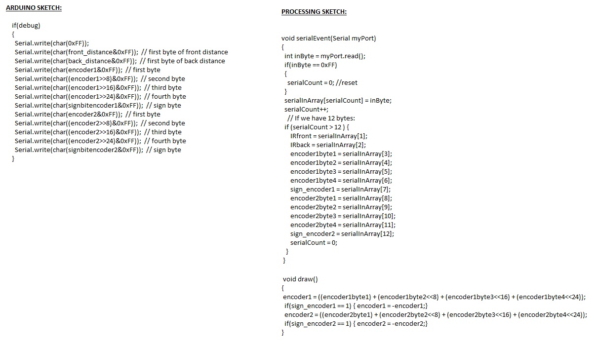
The code for this project was mostly taken from the Arduino Robotics book.    I made minor adjustments to add code to control the AX12a's, and to easily add or remove certain parts of the robot from the code (eg debug, servo, gun, motors can be set to 0 or 1 to turn them off or on).  I also had to use a running average because the servos "jittered" without it.  There was some noise in the input pulses, and the servos were sensitive enough to respond to it.

The code makes used of mixed steering, meaning that the x and y axes on a single joystick are used to control the robot.  It struggled at first to understand how the code from the book worked, and so recently I used Processing to create a program which helps me to visualize the steering.  The picture is of a coordinate system which represents the possible positions of the joystick.  Each point on the coordinate system has two vectors which represent the left motor power (in red) and the right motor power (in blue).  The robot will turn in the direction opposite the larger vector.    In the triangles labelled "1", the robot moves forward but is steered to one side or the other.  In the locations labelled "B", the robot moves directly forward or backwards.  A deadband is used in the program and is represented on the coordinate axes by light vertical lines.  In the locations labelled "2", the robot does a "swing turn" with the motors moving in opposite directions but with different powers.  In the locations labelled "A", the robot executes a pivot turn (as though on a dime), with the speed varying according to how far the joystick is pressed.  There is a deadband in the horizontal direction as well, represented by the two light horizontal lines.  The square in the middle is where the joystick is centered so neither wheel turns.  The Processing code which generated the picture can be seen here.

You can check out the code here, or download the Arduino file directly by clicking here.


Automated Bubble Gun


This project was an outgrowth of the explorer bot project.  I wanted that project to have a modular automated item which could mount on the turret.  One of my ideas was an automated bubble gun.  I found this bubble gun online and ordered a couple to play with.

My initial thought was that it would be very easy to automate this gun by simply having a switched power supply connected to an RC remote control and wiring the motor on the inside of the bubble gun to the power supply.  Turning on and off the motor would deliver bubbles, right?

I tried this but it failed.  It was clear from a simple test that bubbles didn't come out... the motor spun and bubble fluid moved through a hose from the reservoir to the top, where air from a fan was blowing out, but not bubbles.  After some testing, I realized that there is a mechanical arm which sweeps fluid across a "wand".  This creates a membrane of fluid which starts the bubbles forming.  Without that mechanical sweeping action, no bubbles will form.

When you press the trigger on the bubble gun, it both turns on the motor and also sweeps fluid across the wand.  Sometimes you have to press and release the trigger a couple times before the steady stream of bubbles starts to occur.

So to automate the bubble gun, I really needed something to pull and release the trigger.  I considered servos, solenoids, and linear actuators.   Servos are easy to work with but require some thought to turn rotary into linear motion .  Solenoids are great but they draw a lot of current continuously while they are activated.  I actually tried out this low voltage solenoid, but it didn't have enough pulling power to move the trigger.  In the end I was able to get a linear actuator to work... I used the Firgelli L12 series linear actuator.  The specifications are here.  A linear actuator delivers very strong force for its size, and is smart enough to stop drawing power at the end of its stroke.  However, the trick is that you have to reverse the polarity of its power supply to make it move in the opposite direction.  You also pay for what you're getting... these are NOT cheap!

Reversing the polarity was a trick I worked on for some time, because all I had was a switched, variable power supply from the ExplorerBot, with a maximum current draw of about 1.5 Amps.  After some rooting around, I stumbled upon this website for timing circuits using the 555 timer.   The author has an idea for using a 555 timer to reverse a model railroad so it can oscillate back and forth along an open ended track.  The idea uses a single pull double throw (SPDT) relay with an ingenuous routing of the switched pins so that the polarity going to the train can be switched.

I modified this schema as shown in the diagram at right, and mocked up this circuit on a protoboard.  I used a 100 uF capacitor that was sitting around, and then used 100k potentiometers for R1 and R2 (R0 was redundant and omitted).  This allowed me to adjust the switched on and off times in the range of 1-14 seconds, which I figured was reasonable.  See here for a 555 calculator.  The timer worked and the output switched perfectly, so I tried to hook it up to the motor and to the linear actuator.  This is a little tricky because the motor was running off 4.5V, while the linear actuator was supposed to run off of 5-6V.  I set the input voltage at 6V then ran the motor in series with two diodes to drop the voltage by 1.4 V (voltage drops 0.7V across a standard diode).  However, I found in this configuration that the 555 timer started acting erratically and the SPDT relay was switching unreliably.  This was with 4 AA batteries as the input, which should be pretty stiff, but perhaps with the power draw of the motor and the linear actuator, the voltage to the 555 or the voltage seen by the relay pin were dropping too low.  Typically I'll use two separate and isolated power supplies when using relays, so I decided to do the same here.  The bubble gun had come with space for 3AAA batteries, which provided enough voltage to drive the 555 circuit and the relay.  The 4.5V circuit could be completely isolated from the 6V input circuit which was driving the bubble gun motor and the linear actuator.  This worked on the protoboard, so I made a printed circuit board.

The final circuit configurations are shown below.  You can download the Eagle PCB files here.


The finished circuit board is shown at left.  There are four input/output sets of pins for the 4.5V input from the 3AAA batteries in the bubble gun, for the 6V switched input from the explorer bot, to the motor for the bubble gun, and to the linear actuator for the bubble gun.  Note that while the polarity of the linear actuator switches, the polarity to the motor does not (otherwise the motor would spin backwards and the LED might fry!).  The motor only runs when the linear actuator pulls in the trigger.
Although it looks ghetto, it worked fine to attach the
linear actuator with zip ties, and to use a third
zip tie to actually pull the trigger.
A separate switch turns on and off the 3AAA batteries which
power the 555 chip and the relay.  So this switch remains on,
 while the 6V supply is switched
on the ExplorerBot remote control.


After all of that work, the bubble gun still doesn't work great.  I don't think that the problem is actually with the electronics or the way that I'm actuating the device.  I think it has something to do with the motor spinning too fast and blowing too much air thus blowing through the film over the wand and preventing further bubbles from forming until the actuator completes another circuit.    Another possibility is that there is something special about the bubble liquid that comes with the gun...anyhow, I got frustrated and decided the return on investment wasn't really worth additional time on this project.