 This project was an outgrowth of the explorer bot project. I wanted that project to have a modular automated item which could mount on the turret. One of my ideas was an automated bubble gun. I found this bubble gun online and ordered a couple to play with.
My initial thought was that it would be very easy to automate this gun by simply having a switched power supply connected to an RC remote control and wiring the motor on the inside of the bubble gun to the power supply. Turning on and off the motor would deliver bubbles, right?
 When you press the trigger on the bubble gun, it both turns on the motor and also sweeps fluid across the wand. Sometimes you have to press and release the trigger a couple times before the steady stream of bubbles starts to occur.
So to automate the bubble gun, I really needed something to pull and release the trigger. I considered servos, solenoids, and linear actuators. Servos are easy to work with but require some thought to turn rotary into linear motion . Solenoids are great but they draw a lot of current continuously while they are activated. I actually tried out this low voltage solenoid, but it didn't have enough pulling power to move the trigger. In the end I was able to get a linear actuator to work... I used the Firgelli L12 series linear actuator. The specifications are here. A linear actuator delivers very strong force for its size, and is smart enough to stop drawing power at the end of its stroke. However, the trick is that you have to reverse the polarity of its power supply to make it move in the opposite direction. You also pay for what you're getting... these are NOT cheap!
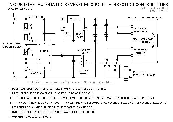 Reversing the polarity was a trick I worked on for some time, because all I had was a switched, variable power supply from the ExplorerBot, with a maximum current draw of about 1.5 Amps. After some rooting around, I stumbled upon this website for timing circuits using the 555 timer. The author has an idea for using a 555 timer to reverse a model railroad so it can oscillate back and forth along an open ended track. The idea uses a single pull double throw (SPDT) relay with an ingenuous routing of the switched pins so that the polarity going to the train can be switched.
The final circuit configurations are shown below. You can download the Eagle PCB files here.


The finished circuit board is shown at left. There are four input/output sets of pins for the 4.5V input from the 3AAA batteries in the bubble gun, for the 6V switched input from the explorer bot, to the motor for the bubble gun, and to the linear actuator for the bubble gun. Note that while the polarity of the linear actuator switches, the polarity to the motor does not (otherwise the motor would spin backwards and the LED might fry!). The motor only runs when the linear actuator pulls in the trigger.

 |
| Although it looks ghetto, it worked fine to attach the linear actuator with zip ties, and to use a third zip tie to actually pull the trigger. |
 |
| A separate switch turns on and off the 3AAA batteries which power the 555 chip and the relay. So this switch remains on, while the 6V supply is switched on the ExplorerBot remote control. |
After all of that work, the bubble gun still doesn't work great. I don't think that the problem is actually with the electronics or the way that I'm actuating the device. I think it has something to do with the motor spinning too fast and blowing too much air thus blowing through the film over the wand and preventing further bubbles from forming until the actuator completes another circuit. Another possibility is that there is something special about the bubble liquid that comes with the gun...anyhow, I got frustrated and decided the return on investment wasn't really worth additional time on this project.