

I finished putting together and testing the GPS Lockbox and it's working great. Assembly was pretty straightforward once I got the staples box. On the top of the box, I lasered out mounting holes for the LEDs, the keypad, and the LCD. I mounted everything using #2.5 screws and some locktite.

Two holes on one wall are used to hold the 5AA battery holder (which was hacked from a 9AA battery holder), and two holes on the adjacent wall hold the I2C GPIO board. The 5AA batteries provide enough voltage to drive the Arduino Micro (specs recommend a minimum of 7V). They also work out great to power the servo (typically servos run on 5-6V max), since that power is switched on and off by an NPN transistor across which there is a voltage drop of about 1.5V (2 diodes at 0.7V each). With fresh batteries, 5 x 1.5V = 7.5V, so the servo sees about 6V.
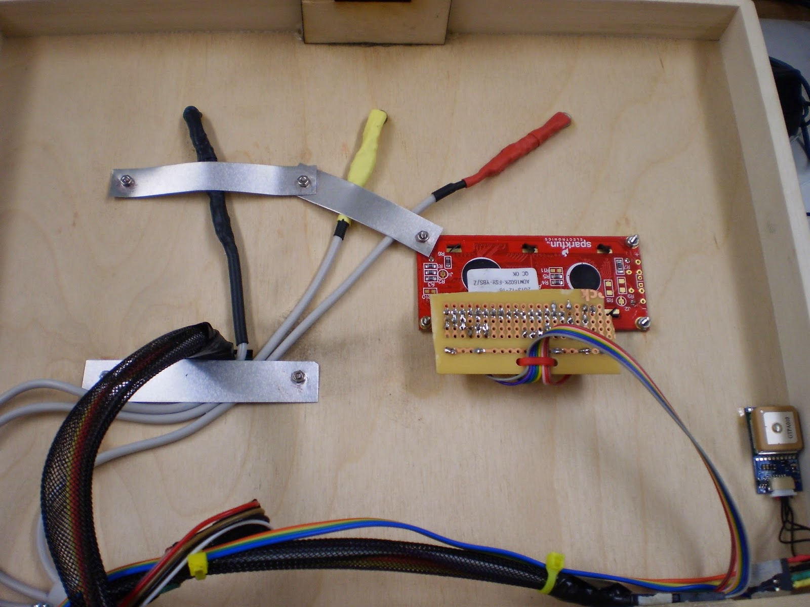
I used very thin aluminum sheet between screws to hold the LEDs in place. I epoxied the GPS on the top inside of the box after testing to make sure it could get a signal through the thin plywood. That was no problem at all.

The servo was mounted using the same laser cut setup as I used for the keypad lockbox. I reinforced the actuator, using a thicker catch meant for a quarter scale servo.

I made a mistake when I glued the servo catch bracket to the inside of the top of the box. As the box lid swung down, the catch hit the bottom of the box. To fix this problem as neatly as possible, I lasered carefully into the bottom edge of the box, as shown above. This actually had to be done from the top of the edge, which was done in several passes adjusting the focus to cut deep enough to remove a section of the wall.

Holes on the bottom hold the custom PCB board in place. I made sure to label all the male headers soldered to the board. I also installed a lighted power switch and even a jumper to switch main power to the servo from +5V from the Arduino Micro to Vin (directly from the 5AA batteries).

Finally, I mounted a USB Micro to USB plug, allowing me to connect to the microprocessor even if the box were locked. The cut isn't very nice because it was done with a dremel.
The code went through minor revisions. One of the "features" added is that the microprocessor now calculates the distance to the target automatically and scales the LED color between blue and red as the user gets closer to the destination. This required a little trickery to get the microprocessor to wait for this distance calculation until it was receiving a valid latitude and longitude. But that was pretty easy since the values from the GPS are zero until it has synced up.

Another feature that was added is that the "B" button now scrolls the user through the display being latitude/longitude, OR time, OR distance to target. The "C" button will lock or unlock the lockbox, which is kind of cheating, but also nice in case it is not working or the user wants to end the game.

Finally, I got the RGB LEDs working in a way which was more helpful. Some weird black magic is preventing logical transitions between green and red (eg yellows don't work). They work fine when outside the rest of the code, but not inside. As an example, the code at left generates red, green and blue values to fade the LEDs from red to green to blue and back to red. The graph below (generated from Serial data from the Arduino) shows that the values are exactly what I want.

"Finished" code is located here: https://github.com/gcronin/GPSLockbox/blob/654401c2bf7ec7e60a410b5dd1b53714a5bf7f1f/GPS_distance/GPS_distance.ino Ugly ugly code (as in hard for someone to understand and has lots of redundant code), but still very effective code (works great)!
PCB board files are linked here (use the ones called micro_board) and pictures of the Eagle schematics are shown below:


Next step; give the box to people for user testing!