Monday, August 29, 2016

Pong in Java: Mouse Controlled Paddle

The previous post discussed command line Java.  I went a little deeper to make two versions of the classic game Pong.  This first one uses the mouse to control one of the paddles.  The other paddle is controlled automatically by the computer.


Java is an object oriented language.  Pong lends itself to programming in this manner because the game is based on objects... specifically a ball and two paddles.  Objects in Java are instances of a class.  A class can contain its own variables, own methods (functions), and requires a constructor which describes how an instance of the class should be created.  For example, the following is the class for a ball:

Each instance of the Ball class has an x-coordinate, y-coordinate, heading, speed, and a diameter.  The diameter is always the same, but the other variables are set when the Ball instance is created.
Elsewhere in the program, an instance of Ball called "ball" is created using the command:

Ball ball = new Ball(200, 100, 30, 10);

The constructor assigns the variables for "ball" (eg its xcor equals 200, etc).

There is also a method for the Ball called "move", which changes the values of xcor and ycor depending on the Ball's speed and heading.


Another object is a Paddle.  The following is the class for a paddle.


This class is similar in many ways to a ball; it has several variables which describe its geometry, but it also interacts with a Ball, and so one variable describes a property of a Ball.

The constructor requires an instance of a Ball to be passed to it:

Paddle leftPaddle = new Paddle(0, 100, 20, 100, ball);

This is important because the "overlaps" method for a Paddle checks to see if the middle of the ball (ballycor + ballDiameter/2) is below the bottom of the paddle (this.ycor + height) or above the top of the paddle (this.ycor).  The relevant geometry is shown below.


The real action for the game happens in the GamePanel class, which includes the methods "paintComponent" and "animate".  "paintComponent" colors two rectangles and an oval at the locations of the left and right paddles, and the ball.  When an instance of GamePanel is created, the constructor requires two Paddles and a Ball.  paintComponent is a method of the class JPanel.  GamePanel extends JPanel, and I have overridden the default method paintComponent.


The "animate" methods causes the ball to move, to deflect off the upper/lower values, and to deflect off of a paddle.  It also causes the right paddle to have the same height location as the ball: rightPaddle.ycor = ball.ycor - rightPaddle.height/2;

The deflection works as follows:  we first check if the ball is within the paddle's width of the left side of the JPanel:  if( ball.xcor  < leftPaddle.width). If so, we want to know if the ball's y-coordinate overlaps with the location of the left paddle.  If so, we do some fancy math to change the heading of the ball so it looks like it bounced off the paddle.   Note that this code does not currently end the game if the paddle and ball don't overlap... the ball goes off the screen to the left, but then it will eventually "bounce" offscreen because the original "if" statement is still true, and the ball will "overlap" with the paddle at some point.  This is a bug.

Next we check to see if the ball is within the paddle's width of the right side of the JPanel:

if(( ball.xcor + ball.ballDiameter)  > getWidth() - rightPaddle.width).  

getWidth() is a built in method for a JPanel which returns the width of the JPanel.  If so, we then check to see if the ball's y-coordinate overlaps with the location of the right paddle, in which case the ball's heading is changed to Pi minus its original heading.

Finally, we check to see if the ball is either at the top of the JPanel (ball.ycor < 0) or at the bottom of the JPanel (ball.ycor > getHeight() - ball.ballDiameter).  In either case, a vertical bounce is done by making the original heading negative.

The class Listener allow the user to interact with the game through the mouse.  Listener implements the interfaces ActionListener and MouseMotionListener.  The latter gives us access to the methods mouseDragged and mouseMoved.  I only use mouseMoved (although you have to override mouseDragged ...my method for mouseDragged does nothing).


When the mouse if moved, it triggers a MouseEvent called e.  We can read the vertical location of the mouse (e.getY()) and then we position the left paddle accordingly.  If the mouse is at the bottom or below the JPanel, the left paddle stays at the bottom of the JPanel.  If the mouse is at the top or above the JPanel, the left paddle stays at the top.  Otherwise, the position of the paddle is set according to the vertical location of the mouse:

gamePanel.leftPaddle.ycor = e.getY() - gamePanel.leftPaddle.height/2;


The ActionListener interface includes the method actionPerformed, which is invoked anytime an action occurs.  Actions are occurring all the time, and so this method occurs constantly.  I have overridden the method to have it call the GamePanel.animate method discussed above.


There is another ActionListener called ButtonListener which includes a timer which is started and stopped by two buttons in the main JPanel, called startButton and stopButton.


The main class for the pong game is a JFrame class called PongGame.  It has no constructor and no instances; everything in the class occurs in the method main.  Main creates a JFrame with two JPanels.  The "top" JPanel (called settingsPanel) includes start and stop buttons.   The other JPanel is the gamePanel already discussed.

In main, we create the ball and two paddles for the left and right sides of the screen.  We create a timer which runs when the start button is pressed and stops when the stop button is pressed.  We create an instance of ButtonListener. We create a Listener so we can have the game animate and detect mouse movement.

I am still confused by aspects of the code.  I know that they work but I just stole them from online.  In particular, these lines are tough:

           Listener listener = new Listener(gamePanel);
      Timer timer = new Timer(50, listener);
      gamePanel.addMouseMotionListener(listener);
      gamePanel.requestFocusInWindow();
   
      ButtonListener buttonListener = new ButtonListener(startButton, stopButton, timer);
      startButton.addActionListener(buttonListener);
      stopButton.addActionListener(buttonListener);


The PongGame class is shown below:
Full code for this game can be found here.

Learning Java: Command Line and LeJos

FIRST switched to Android Studio for robotics coding for the 2015-16 season.  Android Studio is a Java based platform used to create Apps for Android phones.  I spent part of last summer trying to get up to speed with Java.  Rather than dealing with Android Studio (which is a whole different can of worms), I worked with command line Java, and then with Java in NetBeans.

The command line programs described below are on GitHub at https://github.com/gcronin/LearningJava.

Program 1: Parabola
This program uses the scanner to take in  the coefficients of a parabola written in standard form, and converts to vertex form.


Here's an example of the output; the parabola y = x^2 + 2x + 5 is equivalent to y = (x+1)^2 + 4 with a vertex at (-1, 4).


Program 2: Distance Formula
Using the scanner again, the user inputs the x and y coordinates of two points, and the program calculates the distance between the points.


Here's an output showing that the distance between (0,0) and (1,1) is the square root of 2.


Program 3: Add Text to a File
This very simple program requires dealing with exceptions, which is a big part of Java.  When you open and write to a file, you must catch two exceptions... the first is given if the file doesn't exist, and the second is given if the program cannot write to the file.  We deal with exceptions by using the Try... Catch syntax.

A much more complex version of this program with user input can be found here (I didn't write it).


Using LeJos:  Java for NXT:
You can program a LEGO NXT in Java.  One of my students setup the compiler for me.  Once LeJos is installed on your computer, you first need to turn .java files into .class files using "nxjc".  Then you need to use "nxjlink" to create an "nxj" file from one of your class files.  Finally, you use "nxjupload" to upload the .nxj file.  In total, this series of commands will do the work for you:

nxjc *.java  //create .class files from .java files
set /p mclass= "Please enter the name of the main class file: " %=%  //chose a .class file
nxjlink -o linked.nxj %mclass%  //create linked.nxj from the .class file
nxjupload -r *nxj   //upload linked.nxj to the NXT


Here are a few Java programs for the NXT:
 This program just prints "Hello World" to the screen until any button is pressed.
This program shows the value of a light sensor attached to port 1 in several different formats.
This program moves motors attached to ports B and C at 50% power.
This program is a line follower using PID control.  I am not sure that it has been tuned correctly, as it was written by a former student.


Sunday, August 28, 2016

Fun with H-Bridges

This summer in our school's robotics camp, participants worked with the Adafruit Mini Rover Chassis Kit.  For $25, it looks like a steal.  However, the motors turn out to be tiny DC motors and not continuous servos, and so speed control requires circuitry beyond a microprocessor.

There are three basic ways to control a motor.  If you want to simply turn the motor on and off, you can use a switch wired directly to the power for the motors.  The breadboard below shows that setup on a Parallax Board of Education Shield.


If you want to digitally control the speed of a motor (in addition to turning it on or off), you can use a transistor.  In the picture below, a bipolar 2N2222 is wired to a PWM output of a microprocessor to allow for speed control via the duty cycle.


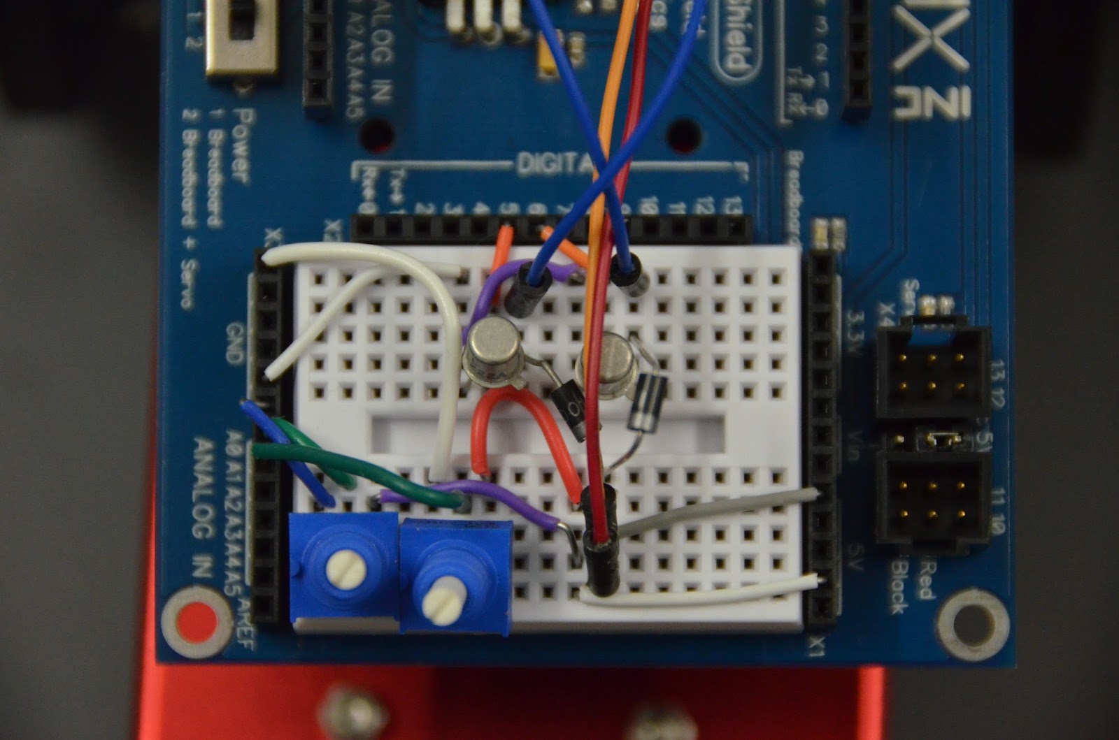
Finally, if you want full speed AND direction control over motors, you need an H-bridge.  I've made H-bridges before (see the Explorer Bot), but I figured it was time to make a simpler one which could be used for educating students using the Mini Rover Chassis Kit.


The result is shown in the picture above.  It uses two 2N2907 PNP transistors in the upper legs, and
two 2N2222 NPN transistors in the lower legs.  There are two H-bridges, one for the left motor and one for the right motor.  All eight transistors are wired to separate digital outputs on an Arduino, with the NPN transistors controlled by PWM pins.  This allows for speed control.  Potentiometers control the speed and direction in the test code.


Schematics, Eagle CAD board files, and test code is published on GitHub at https://github.com/gcronin/H-bridge.

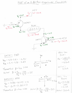
I also measured some voltages and currents for one leg of an H-bridge, and then analyzed the circuit from the point of view of both a physicist and an electrical engineer.


Thursday, May 26, 2016

Water Pump

This is a water pump fabricated from scratch based on the directions of Gerald Recktenwald at Portland State University, found here: https://learn.sparkfun.com/resources/44.  The housing was constructed from PVC plastic using a mill, mostly used as a precise drill press.  A centered N size through hole fits a bronze bushing and o-ring seat for the motor shaft.  On the other side, a 1" forstner bit is used to make the cylindrical chamber for the impeller (yellow) and a 1.25" forstner bit makes a seat for an o-ring.  On the top of the grey and the middle of the clear sheet, two Q sized holes are tapped with a 1/4" NPT pipe threads for the barbed hose connectors.  Four holes allow a zip tie to hold the motor in place.  Finally, the clear and grey pieces were attached with screws to compress an o-ring, sealing the other side of the pump from water.

The bronze bearing was fabricated on a lathe.  A through hole was drilled concentric to the outer diameter of a bronze rod.  The end of the rod was beveled to allow it to be pressed into the N hole mentioned above.  A small seat was made with an end mill to house the tiny o-ring which sealed the motor shaft from water.  The rod was then parted to make the bearing.

Finally, an impeller was fabricated on a Makerbot 3D printer from a design I created in Solidworks.  The impeller is not anything fancy, and is not optimized at all.  Part of the point of this project for students is to design their own impellers and then to test the efficiency of the pump.  Nevertheless, the pump worked when I tested it (at least as soon as i figured out which side was the inlet and outlet).

In the video below, you can see that the pump can supply a limited amount of potential energy; as the outlet tube is raised, the flow rate diminishes until its maximum pumping height is reached where the flow rate is zero.


Thursday, May 19, 2016

Simple Wearables

Just a couple of fun wearables.  All run by the Lily Twinkle which outputs random signals to four LEDs.  The LEDs were sewn on with conductive thread.  
The yellow wearables are headbands which were used by the drive team of FTC Team 5619.  The beige has conductive velcro which turns on the device when the bracelet is put on as shown in the video below.

Tuesday, May 10, 2016

Oscillating Fan

A seemingly simple project is notable for two reasons.  First it took me on a long wild goose chase to control the jitter in a micro hobby servo, and second, it gave me a reason to really teach myself transistor physics.

This project was to serve as a demonstration model for a robotics class that I teach.  I lifted the curriculum without shame from Gerald Recktenwald at Portland State University  The project is an exercise in design for the laser cutter, and in control of servos and DC motors using PWM, transistors, switches, potentiometers, and servo pulses.

I made several ill-advised mistakes early on the project.  The first was to test the components individually, and then expect them to work together.  In this case, the components were a micro-switch, a Solarbotics A108 microservo, a 10k potentiometer, a 2N2222 transistor and a toy DC motor.  Test programs showed that the servo worked fine with the Arduino Servo library, and that separately the transistor drove the DC motor fine with speed varying based on the angle of the potentiometer.  All pretty standard stuff.

I made a little stand for the servo and a holder for the motor on the laser.  I milled a PCB board, soldered all the components in place, mounted the servo and the motor, and gave it a run.  The servo worked fine, as did the sensors, but the toy motor did nothing.  A quick search online revealed that the servo library uses Timer 1 on the Arduino to control pulse widths.  Timer 1 also controlled PWM pins 9 and 10, and my transistor base was being driven by pin 9.  Damn.  I didn't see this conflict until I ran all the components in the same Arduino sketch.

So I removed the PCB, went back to a breadboard setup and wired the servo to pin 3, leaving the fan in pin 9.
The DC motor and the servo both worked now, but there was a new unexpected behavior.  The servo would twitch like crazy when the fan was on.  Interestingly, the servo seemed to be fine when the fan was off.   See the video.

This is where I made my second mistake.  Based on the research I had just conducted with timers, I figured that somehow the fan was messing up the timing of the servo, resulting in varying pulse widths and hence the jitter of the servo.  I chose not to look at an oscilloscope; instead I went into research mode and looked at ways to make my own pulses.  

My understanding of timers and generating pulses is based on the website "The Perfect Pulse" of "Josh". There are three timers for the atmega328, timers 0, 1 and 2.  Timers 0 and 2 are 8 bit timers, meaning that you start counting at 0 and end at 2^8 - 1 = 255 before restarting at 0.  Timer 1 is a 16 bit timer, so it counts from 0 to 2^16 - 1= 65535.  Timer 0 is used by the Arduino function millis and delay.  It is also used for PWM pins 5 and 6.  Timer 1 is used by the Servo library and also controls PWM pins 9 and 10.  Finally, Timer 2 is used by the tone() function and PWM pins 3 and 11.  

Josh's perfect pulse uses timer 2.  There are two bytes associated with timer two:
  
TCCR2A


COM2A1
COM2A0
COM2B1
COM2B0
Reserved
Reserved
WGM21
WGM20
Compare output mode
Compare output mode


Waveform generation bit
TCCR2B


FO2A
FO2B
Reserved
Reserved
WGM22
CS22
CS21
CS20


Waveform generation bit
Prescaler
Prescaler
Prescaler

The basic rule is that there is a counter which ticks at a certain rate.  It can tick at the CPU clock speed, but you can also change the prescaler values in order to divide the CPU clock rate and slow the counter down.  

The counter (TCNT2) starts at 0, and when it reaches a variable called OCR2A (the "top"), it resets to zero.  The timer can be linked to an output pin (3 or 11 for timer 2 based on the first four bits of TCCR2A).  When the counter resets to 0, the output pin is set low.  If at anypoint the counter equals a second variable called OCR2B (the "match"), the output pin is set high.  By changing the value of the "match" variable (between 0 and 255) and by modifying the prescaler values, you can generate tons of patterns including a customized PWM signal or a servo control signal.

The important variables are shown below. 
//              counter       TCNT2
//              TOP    OCR2A
//              MATCH  OCR2B

The base pulse program that I pulled offline works as follows.  We set the following bits equal to one:   COM2B1, COM2B0, WGM21, WGM20, WGM22.  The WGM bits setup a particular mode of using the counter (Fast PWM Mode 7), which is the one I am describing.  I don’t understand the other modes.   

The easy way to set bits is using _BV( bit name), which sets bit name to 1.  For example,
TCCR2A = _BV(COM2B0) | _BV(COM2B1) | _BV(WGM20) | _BV(WGM21);
Makes COM2B1, COM2B0, WGM21, and WGM20 equal to 1.  The definition of _BV(bit) is 1<<bit

We setup the prescaler bits
//  Clock Select Bits:  set with TCCR2B
//     CS22    CS21   CS20
//     0        0        0    //timer/counter stopped
//     0       0         1   // no prescaler
//     0       1         1   // /32 prescaler
//     1       0         0   // /64 prescaler
//     1       0         1   // /128 prescaler
//     1       1         0   // /256 prescaler
//     1       1         1   // /1024 prescaler

We attach an output pin to the timer: 
DDRD |= _BV(3);     // Set pin to output (Note that OC2B = GPIO port PD3 = Digital Pin 3)

To tread water, we set
  TCNT2 = 0x00;     // Start counting at bottom.
  OCR2A = 0;      // Set TOP to 0.

These means that the counter starts at zero, the top is zero, and so the counter remains zero always.  Any attached pin is kept low.     

There are three functions that I use:
    OSP_SET_WIDTH(width)
    OSP_FIRE()
    OSP_INPROGRESS()

The first sets the value of the MATCH bit to be 255 – (width – 1):  #define OSP_SET_WIDTH(cycles) (OCR2B = 0xff-(cycles-1))

The second function sets the counter to be one less than the match:  #define OSP_FIRE() (TCNT2 = OCR2B - 1).  This means that on the next counter increment, the output (pin 3 in this case) will go high, and will stay high until the counter reaches top.  Note that since the top is 255, and match = 255 – (width – 1), the duration of the pulse will be whatever width is.

The final function is the boolean TCNT2>0.   It is used in my program to delay until the pulse is done by using a blank while loop:  while (OSP_INPROGRESS());

The picture here is an illustration of a sample pulse with width 10.  The OSP_FIRE() function is run at time t0.  This sets the counter equal to 245.  On the next cycle (counter = 246, time t1), output pin 3 goes high.  It stays high until the counter reaches 255 (time t2).  Then the counter resets and the output pin 3 goes low.  The pulse stayed on while the counter went from 246 to 255, which is 10 counts.


I measured pulse widths for some values of the prescaler using an oscilloscope.  In all cases I set “width” = 10. 
Prescaler
Pulse Width
Calculated Time per count
32
20 us
2 us
64
40 us
4 us
128
80 us
8 us
256
160 us
16 us
1024
646 us
64.6 us

For the servo control signal, we need pulses between 1-2ms with a period of roughly 20ms.   Using the 1024 prescaler, a width of 20 gives 1.28 ms (calculated = 20 x .0646ms = 1.29ms) and a width of 30 gives 1.94 ms (calculated = 30 x 0.0646ms = 1.94ms).  So in the sample program, the width is just adjusted going between 20 and 30 to sweep the servo through its range of values.  A delay of 20ms is used to space the servo pulses to the appropriate frequency.

I created a sketch using pulses which I was generated based on timer 2, and tested the fan again.  Unfortunately the servo still went crazy when the motor was connected.  The final code for this sketch is on Github here

I tried a couple other solutions... the Software Servo library worked great to move a servo, but did not remove the problem related to the motor.  
I tried to clean up the servo power by running the servo with a separate power supply from the rest of the circuity, and by installing an LM7805 voltage regulator with a bunch of different valued capacitors (0.1, 1, 10 uF) across the output.  Neither of these tests made a difference.

Ultimately, I tried a few other servos and saw that the problem seemed to be worst with the Solarbotics A108.  With Hitec servos, the problem was much more understated.  In the end, I picked up a Tower Pro SG90 from Vetco and the problem went away.  

An oscilloscope trace of the servo signal shows that it picks up a lot of noise when the motor is turned on (at about 14 seconds into the video). This was an electrical engineer's take: "I believe the problem comes from electrical noise from the fan motor getting into the Arduino's timing circuits. I'm assuming that it is a PM motor without any filtering. Here is why I say that. In a PM motor as the armature rotates, the brush(s) bridges the space between the commutator bar segments shorting the winding (a coil, right?) between the two adjacent segments. Herein lies the problem: A large Ldi/dt current usually towards the end of commutation causes an arc between the commutator bars. Further, the coil or winding current is reversed when the rotor continues on its journey and the torque direction is preserved. Reversing current is the maximum di/dt, right?  Think of the zero crossing of a sine wave mathematically.  These current spikes can find their way through less than adequate filtering into sensitive high impedance digital circuits." - Larry R.

I interpret his words in the following graph:


Once we had established that the problem was caused by the DC motor, the solution was just to use a servo with better filtering circuitry to ignore the current spikes.  The final prototype is shown in the picture below.
The SoftwareServo code also works fine: code here.
The code I use with my classes, which includes debugging information is located here.

The last piece of this project was a fairly comprehensive document that I wrote on transistor physics.  The picture below links to a webpage which has that document (called transistor.pdf).
  

Friday, April 22, 2016

In-Situ Datalogger for Robots

FTC Team 2856, Tesseract, is one of the robotics teams that I mentor.  As they were preparing for Superregionals this past March, they noticed that they were draining batteries extremely quickly.  The would run maybe two matches on a single battery and then notice that the robot could barely function.

I had a project in the works which seemed like it could help.  About a year previously, I had picked up a 45A AttoPilot current and voltage sensor from Sparkfun.  This simple sensor runs off the input power and has a three pin header for current, voltage and ground which can be sent to a microprocessor.

One of 2856's team members soldered anderson connectors for the input and output lines so that we could put the sensor between the battery and the robot.  I also purchased an SD card shield for Arduino, wired the current, voltage and ground pins to the Arduino, and wrote a program to log data on the SD card.

The final steps were to hack a simple 3D printed box from Thingiverse (http://www.thingiverse.com/thing:18095) to include slots for the Anderson connectors, a hole for a switch, and a slot for the SD card (since my shield had it on the opposite side as this print).  Finally, I made a small PCB with four diagnostic LEDs which tell us if a problem has occurred.

The pictures below show the finished product.


As you can see in the last picture, the four diagnostic LEDs include a power button, a toggling LED which shows when data is written to the SD card, an error light which illuminates if the program failed to detect the SD card, and an error light which illuminates if there is an error writing to the SD card.  These LEDs are very useful, because without them it's impossible to tell whether you have successfully collected data before the SD card is plugged into a laptop.

Data is exported in CSV format in the form shown below.
dataString = String(millis());
dataString += ", ";
dataString += String(VFinal);
dataString += ", ";
dataString += String(IFinal);
 A data set is collected every second.  The program is found here.

2856 made great use of the datalogger by designing a series of experiments which isolated specific systems on the robot and tested them for current draw.  They found that the tank treads were the culprit, pulling upwards of 15Amps at times.  This was sucking our 3000mA-hr battery dry very quickly.  They reduced the friction in the tank treads and lowered the current draw.

In general, when we graph the data, we see that current and voltage are inversely related.  Hence knowing having both is somewhat redundant, although its nice to see how much the voltage sags under load and to see how much current is being consumed.   A little test robot pulled 3-5 A maximum, yet the voltage sometimes sagged from 12V all the way down to 6V.  Probably a pretty old battery!
 

While having the data itself can be very powerful, I thought it would be interesting to go one step further and see if I could visualize the current and voltage in real time.  I wrote a python program which plotted the data in real time on my computer screen.   Script is here.  The program uses matplotlib pyplot and animation.  We read in a csv file stripped of time, with voltage in the first column and current in the second.  Each column is saved as a different array (data[:,0] and data[:,1]).  A new array is setup which is a hack to get the data to be shown at the correct rate.  The total time which passed (found using timestamps from the Arduino data) is divided by the number of samples to find the sampling period.  The new array is a simple arithmetic sequence with the same number of entries as the current data.   Finally, some black magic plots current versus time.  I borrowed widely from the internet and don't 100% understand how the script work.

The video linked below showed a recording on my computer screen as it plots the data.  The quality sucks, but this was just a proof of concept.

Finally, a friend and coworker made a movie showing the robot moving at the same time as the data is being plotted.  The two are close to, but not exactly lined up.  Still, it's obvious that as the robot executes certain motions, the current spikes.  When the robot stops, current drops to zero.  Current jumps drastically as the robot starts from a stop. It stays at a medium value when the robot is stuck (eg running into the wall at 0.42 or stuck on a ball at 0.27).  By the ending the plot is delayed by at least a couple seconds compared with the robot motion.  So as a real tool, it would require much better syncing.