Tuesday, May 10, 2016

Oscillating Fan

A seemingly simple project is notable for two reasons.  First it took me on a long wild goose chase to control the jitter in a micro hobby servo, and second, it gave me a reason to really teach myself transistor physics.

This project was to serve as a demonstration model for a robotics class that I teach.  I lifted the curriculum without shame from Gerald Recktenwald at Portland State University  The project is an exercise in design for the laser cutter, and in control of servos and DC motors using PWM, transistors, switches, potentiometers, and servo pulses.

I made several ill-advised mistakes early on the project.  The first was to test the components individually, and then expect them to work together.  In this case, the components were a micro-switch, a Solarbotics A108 microservo, a 10k potentiometer, a 2N2222 transistor and a toy DC motor.  Test programs showed that the servo worked fine with the Arduino Servo library, and that separately the transistor drove the DC motor fine with speed varying based on the angle of the potentiometer.  All pretty standard stuff.

I made a little stand for the servo and a holder for the motor on the laser.  I milled a PCB board, soldered all the components in place, mounted the servo and the motor, and gave it a run.  The servo worked fine, as did the sensors, but the toy motor did nothing.  A quick search online revealed that the servo library uses Timer 1 on the Arduino to control pulse widths.  Timer 1 also controlled PWM pins 9 and 10, and my transistor base was being driven by pin 9.  Damn.  I didn't see this conflict until I ran all the components in the same Arduino sketch.

So I removed the PCB, went back to a breadboard setup and wired the servo to pin 3, leaving the fan in pin 9.
The DC motor and the servo both worked now, but there was a new unexpected behavior.  The servo would twitch like crazy when the fan was on.  Interestingly, the servo seemed to be fine when the fan was off.   See the video.

This is where I made my second mistake.  Based on the research I had just conducted with timers, I figured that somehow the fan was messing up the timing of the servo, resulting in varying pulse widths and hence the jitter of the servo.  I chose not to look at an oscilloscope; instead I went into research mode and looked at ways to make my own pulses.  

My understanding of timers and generating pulses is based on the website "The Perfect Pulse" of "Josh". There are three timers for the atmega328, timers 0, 1 and 2.  Timers 0 and 2 are 8 bit timers, meaning that you start counting at 0 and end at 2^8 - 1 = 255 before restarting at 0.  Timer 1 is a 16 bit timer, so it counts from 0 to 2^16 - 1= 65535.  Timer 0 is used by the Arduino function millis and delay.  It is also used for PWM pins 5 and 6.  Timer 1 is used by the Servo library and also controls PWM pins 9 and 10.  Finally, Timer 2 is used by the tone() function and PWM pins 3 and 11.  

Josh's perfect pulse uses timer 2.  There are two bytes associated with timer two:
  
TCCR2A


COM2A1
COM2A0
COM2B1
COM2B0
Reserved
Reserved
WGM21
WGM20
Compare output mode
Compare output mode


Waveform generation bit
TCCR2B


FO2A
FO2B
Reserved
Reserved
WGM22
CS22
CS21
CS20


Waveform generation bit
Prescaler
Prescaler
Prescaler

The basic rule is that there is a counter which ticks at a certain rate.  It can tick at the CPU clock speed, but you can also change the prescaler values in order to divide the CPU clock rate and slow the counter down.  

The counter (TCNT2) starts at 0, and when it reaches a variable called OCR2A (the "top"), it resets to zero.  The timer can be linked to an output pin (3 or 11 for timer 2 based on the first four bits of TCCR2A).  When the counter resets to 0, the output pin is set low.  If at anypoint the counter equals a second variable called OCR2B (the "match"), the output pin is set high.  By changing the value of the "match" variable (between 0 and 255) and by modifying the prescaler values, you can generate tons of patterns including a customized PWM signal or a servo control signal.

The important variables are shown below. 
//              counter       TCNT2
//              TOP    OCR2A
//              MATCH  OCR2B

The base pulse program that I pulled offline works as follows.  We set the following bits equal to one:   COM2B1, COM2B0, WGM21, WGM20, WGM22.  The WGM bits setup a particular mode of using the counter (Fast PWM Mode 7), which is the one I am describing.  I don’t understand the other modes.   

The easy way to set bits is using _BV( bit name), which sets bit name to 1.  For example,
TCCR2A = _BV(COM2B0) | _BV(COM2B1) | _BV(WGM20) | _BV(WGM21);
Makes COM2B1, COM2B0, WGM21, and WGM20 equal to 1.  The definition of _BV(bit) is 1<<bit

We setup the prescaler bits
//  Clock Select Bits:  set with TCCR2B
//     CS22    CS21   CS20
//     0        0        0    //timer/counter stopped
//     0       0         1   // no prescaler
//     0       1         1   // /32 prescaler
//     1       0         0   // /64 prescaler
//     1       0         1   // /128 prescaler
//     1       1         0   // /256 prescaler
//     1       1         1   // /1024 prescaler

We attach an output pin to the timer: 
DDRD |= _BV(3);     // Set pin to output (Note that OC2B = GPIO port PD3 = Digital Pin 3)

To tread water, we set
  TCNT2 = 0x00;     // Start counting at bottom.
  OCR2A = 0;      // Set TOP to 0.

These means that the counter starts at zero, the top is zero, and so the counter remains zero always.  Any attached pin is kept low.     

There are three functions that I use:
    OSP_SET_WIDTH(width)
    OSP_FIRE()
    OSP_INPROGRESS()

The first sets the value of the MATCH bit to be 255 – (width – 1):  #define OSP_SET_WIDTH(cycles) (OCR2B = 0xff-(cycles-1))

The second function sets the counter to be one less than the match:  #define OSP_FIRE() (TCNT2 = OCR2B - 1).  This means that on the next counter increment, the output (pin 3 in this case) will go high, and will stay high until the counter reaches top.  Note that since the top is 255, and match = 255 – (width – 1), the duration of the pulse will be whatever width is.

The final function is the boolean TCNT2>0.   It is used in my program to delay until the pulse is done by using a blank while loop:  while (OSP_INPROGRESS());

The picture here is an illustration of a sample pulse with width 10.  The OSP_FIRE() function is run at time t0.  This sets the counter equal to 245.  On the next cycle (counter = 246, time t1), output pin 3 goes high.  It stays high until the counter reaches 255 (time t2).  Then the counter resets and the output pin 3 goes low.  The pulse stayed on while the counter went from 246 to 255, which is 10 counts.


I measured pulse widths for some values of the prescaler using an oscilloscope.  In all cases I set “width” = 10. 
Prescaler
Pulse Width
Calculated Time per count
32
20 us
2 us
64
40 us
4 us
128
80 us
8 us
256
160 us
16 us
1024
646 us
64.6 us

For the servo control signal, we need pulses between 1-2ms with a period of roughly 20ms.   Using the 1024 prescaler, a width of 20 gives 1.28 ms (calculated = 20 x .0646ms = 1.29ms) and a width of 30 gives 1.94 ms (calculated = 30 x 0.0646ms = 1.94ms).  So in the sample program, the width is just adjusted going between 20 and 30 to sweep the servo through its range of values.  A delay of 20ms is used to space the servo pulses to the appropriate frequency.

I created a sketch using pulses which I was generated based on timer 2, and tested the fan again.  Unfortunately the servo still went crazy when the motor was connected.  The final code for this sketch is on Github here

I tried a couple other solutions... the Software Servo library worked great to move a servo, but did not remove the problem related to the motor.  
I tried to clean up the servo power by running the servo with a separate power supply from the rest of the circuity, and by installing an LM7805 voltage regulator with a bunch of different valued capacitors (0.1, 1, 10 uF) across the output.  Neither of these tests made a difference.

Ultimately, I tried a few other servos and saw that the problem seemed to be worst with the Solarbotics A108.  With Hitec servos, the problem was much more understated.  In the end, I picked up a Tower Pro SG90 from Vetco and the problem went away.  

An oscilloscope trace of the servo signal shows that it picks up a lot of noise when the motor is turned on (at about 14 seconds into the video). This was an electrical engineer's take: "I believe the problem comes from electrical noise from the fan motor getting into the Arduino's timing circuits. I'm assuming that it is a PM motor without any filtering. Here is why I say that. In a PM motor as the armature rotates, the brush(s) bridges the space between the commutator bar segments shorting the winding (a coil, right?) between the two adjacent segments. Herein lies the problem: A large Ldi/dt current usually towards the end of commutation causes an arc between the commutator bars. Further, the coil or winding current is reversed when the rotor continues on its journey and the torque direction is preserved. Reversing current is the maximum di/dt, right?  Think of the zero crossing of a sine wave mathematically.  These current spikes can find their way through less than adequate filtering into sensitive high impedance digital circuits." - Larry R.

I interpret his words in the following graph:


Once we had established that the problem was caused by the DC motor, the solution was just to use a servo with better filtering circuitry to ignore the current spikes.  The final prototype is shown in the picture below.
The SoftwareServo code also works fine: code here.
The code I use with my classes, which includes debugging information is located here.

The last piece of this project was a fairly comprehensive document that I wrote on transistor physics.  The picture below links to a webpage which has that document (called transistor.pdf).
  

Friday, April 22, 2016

In-Situ Datalogger for Robots

FTC Team 2856, Tesseract, is one of the robotics teams that I mentor.  As they were preparing for Superregionals this past March, they noticed that they were draining batteries extremely quickly.  The would run maybe two matches on a single battery and then notice that the robot could barely function.

I had a project in the works which seemed like it could help.  About a year previously, I had picked up a 45A AttoPilot current and voltage sensor from Sparkfun.  This simple sensor runs off the input power and has a three pin header for current, voltage and ground which can be sent to a microprocessor.

One of 2856's team members soldered anderson connectors for the input and output lines so that we could put the sensor between the battery and the robot.  I also purchased an SD card shield for Arduino, wired the current, voltage and ground pins to the Arduino, and wrote a program to log data on the SD card.

The final steps were to hack a simple 3D printed box from Thingiverse (http://www.thingiverse.com/thing:18095) to include slots for the Anderson connectors, a hole for a switch, and a slot for the SD card (since my shield had it on the opposite side as this print).  Finally, I made a small PCB with four diagnostic LEDs which tell us if a problem has occurred.

The pictures below show the finished product.


As you can see in the last picture, the four diagnostic LEDs include a power button, a toggling LED which shows when data is written to the SD card, an error light which illuminates if the program failed to detect the SD card, and an error light which illuminates if there is an error writing to the SD card.  These LEDs are very useful, because without them it's impossible to tell whether you have successfully collected data before the SD card is plugged into a laptop.

Data is exported in CSV format in the form shown below.
dataString = String(millis());
dataString += ", ";
dataString += String(VFinal);
dataString += ", ";
dataString += String(IFinal);
 A data set is collected every second.  The program is found here.

2856 made great use of the datalogger by designing a series of experiments which isolated specific systems on the robot and tested them for current draw.  They found that the tank treads were the culprit, pulling upwards of 15Amps at times.  This was sucking our 3000mA-hr battery dry very quickly.  They reduced the friction in the tank treads and lowered the current draw.

In general, when we graph the data, we see that current and voltage are inversely related.  Hence knowing having both is somewhat redundant, although its nice to see how much the voltage sags under load and to see how much current is being consumed.   A little test robot pulled 3-5 A maximum, yet the voltage sometimes sagged from 12V all the way down to 6V.  Probably a pretty old battery!
 

While having the data itself can be very powerful, I thought it would be interesting to go one step further and see if I could visualize the current and voltage in real time.  I wrote a python program which plotted the data in real time on my computer screen.   Script is here.  The program uses matplotlib pyplot and animation.  We read in a csv file stripped of time, with voltage in the first column and current in the second.  Each column is saved as a different array (data[:,0] and data[:,1]).  A new array is setup which is a hack to get the data to be shown at the correct rate.  The total time which passed (found using timestamps from the Arduino data) is divided by the number of samples to find the sampling period.  The new array is a simple arithmetic sequence with the same number of entries as the current data.   Finally, some black magic plots current versus time.  I borrowed widely from the internet and don't 100% understand how the script work.

The video linked below showed a recording on my computer screen as it plots the data.  The quality sucks, but this was just a proof of concept.

Finally, a friend and coworker made a movie showing the robot moving at the same time as the data is being plotted.  The two are close to, but not exactly lined up.  Still, it's obvious that as the robot executes certain motions, the current spikes.  When the robot stops, current drops to zero.  Current jumps drastically as the robot starts from a stop. It stays at a medium value when the robot is stuck (eg running into the wall at 0.42 or stuck on a ball at 0.27).  By the ending the plot is delayed by at least a couple seconds compared with the robot motion.  So as a real tool, it would require much better syncing.
 

Saturday, May 16, 2015

Wakeup Light Alarm

I met a friend recently who mentioned that she was annoyed with her alarm, which used sounds and clicked whenever it was about to wake her up.  She awoke to the click rather than to the gentle sounds of the alarm.  They sell alarms which gently use light as an alarm, but they are expensive.  With a couple items sitting around, I made a prototype of a lighting alarm.

To set the time and the alarm, you use 10K pots which are attached to the analog inputs of the microprocessor, which is a Sparkfun 3v3 Arduino Pro Mini (atmega328 running at 8MHz).


The alarm is triggered when the time and the alarm are the same.  This leads to a progressively increasing intensity of an Adafruit Neopixels LED strip, which also shifts colors from RGB  245,99,144 (pink), to RGB  255,254,60 (yellow).   The alarm duration can be adjusted with a third potentiometer from a minimum of one minute to a maximum of about 8 minutes.  


I used an OLED from sparkfun for the display.  The OLED runs at 3v3, which is why I used the pro-mini board.   It is an outstanding little device with incredible resolution given its small size.   I wired it up using the SPI interface exactly according to the directions on the sparkfun tutorial website.  

I used a switching 5V power supply with 8A capacity to drive both the microprocessor and the board.  Interestingly, the power supply initially failed to turn on the LEDs.  They worked fine with the 5V pins from an ATX computer power supply, and also from 3AA batteries.  At first I figured that the power from the supply I had bought was too puny, but I tried another 5V supply and it also failed.  After a little research, I realized that the logic supply to the Neopixels was being driven at 3v3 from the Arduino Pro Mini, while the LEDs are being driven at 5V.  If the power supply is nice and stiff, the 3v3 voltage rests in "no-man's land" in terms of logic... it is not high enough to be "1".  The solution in my case was to install a 3A capacity diode (IN5401, datasheet) in series with the power supply, to drop the 5V down to 4.3V.  This fixed that problem, although the diode does run a bit hot in testing.  I also installed a 1000 uF capacitor across the 5V supply to protect the Neopixels from damaging startup current surges.

All of the components were mounted on a custom PCB board.

The potentiometers used were 3310Y-001-103L 10k.  I love them cause you can super glue lego pins on the top easily.  The pots have lego gears as knobs and the center position is marked with white out.

Finally, the LED strip was mounted onto a styrofoam cone.  Paper clips were used to temporarily secure it into the styrofoam, and then epoxy was added to permanently secure the paper clips.  The cone was epoxyed onto a piece of basswood onto which were mounted the PCB board and the power supply.


The coding (available here on Github) was somewhat rote, although figuring out how to give a reasonable range of speeds to adjust the clock and the alarm took some time.  In addition, I tried to make the lighting resemble a sunrise.   It's a reasonable attempt, but nowhere as good as the nature's version.

The algorithm used for the lighting is to pick an initial color and a final color, and linearly interpolate the colors between.  This is easy to do using a formula such as: currentColor = initialColor + currentStep/TotalSteps* (FinalColor - InitialColor).  For example, the raw interpolated colors are shown in the graph below, overlayed with the corresponding colors.
In addition, I wanted the intensity of light to increase, starting from gentle lighting up to very strong lighting.  I used a quadratic function to increase the intensity slowly at the beginning and then at an increasing rate.  The function used is intensity = 0.04 * currentStep^2.  This results in 100% intensity at 50 steps (which is how many are currently set in the program).  The quadratic coefficient could be tweaked so that it was parametric with the number of steps, but I didn't bother for a prototype.

To get the actual color, the raw RGB values are scaled by the intensity value for the current step.  The graph below shows the scaled RGB values and colors.  I think the colors are misleading cause they are subtractive rather than additive as is generated light.

Downloadable Eagle Files and Excel Spreadsheet for color calculations can be downloaded here:  https://sites.google.com/site/rampantrobots/wakeuplight.

Approximate costs:
Sparkfun Pro-Mini Arduino:  $10
OLED:  $18
Newcastle Power Supply:  $15
NeoPixel LED Strip:  $12 (half of full strip used)
Basswood and Styrofoam:  $8
TOTAL:  $63

Tuesday, December 9, 2014

Mood Machine

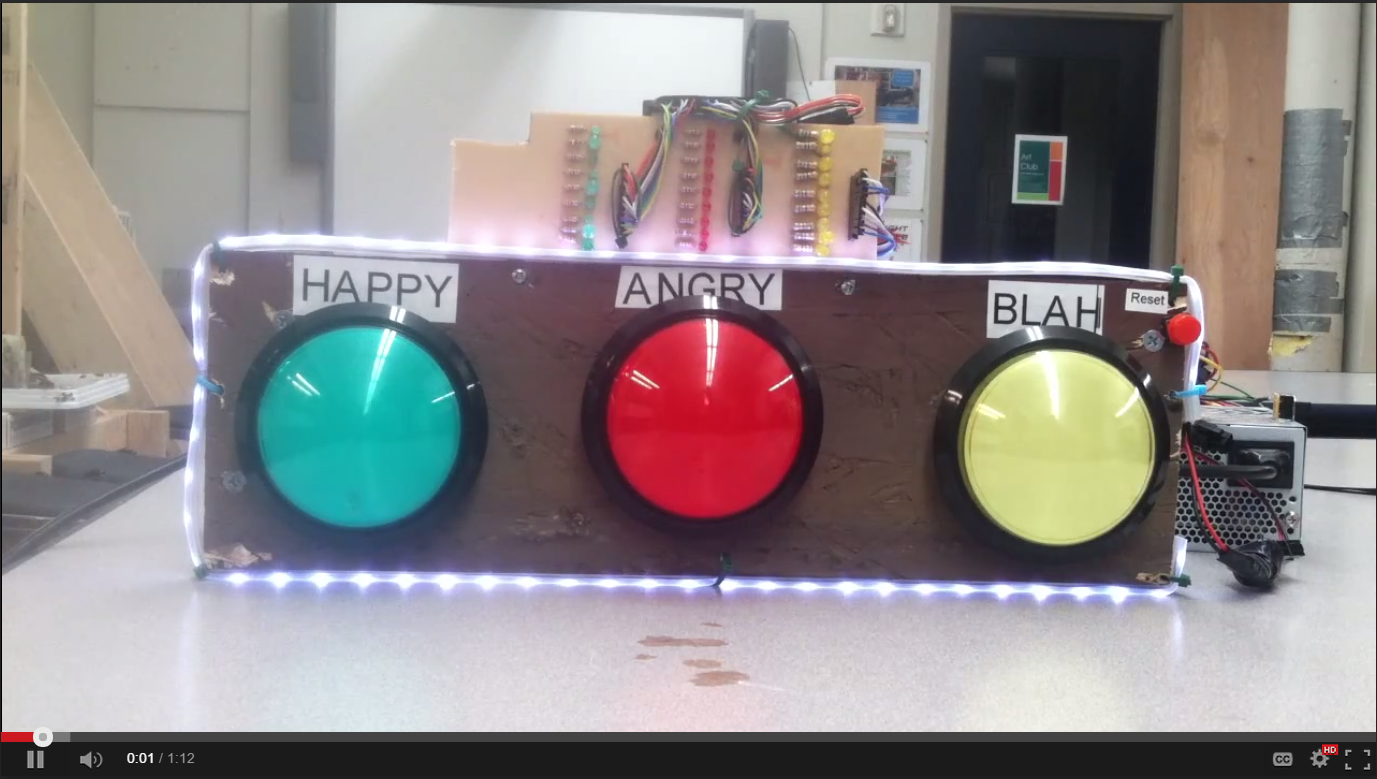
Students in Seattle Academy's robotics elective worked to make and program a Mood Machine.  It is designed to be used by a classroom teacher in order to assess the overall mood of his/her class.


The students were able to describe the contributions they made to the project.


The Mood Machine was based on the fun SparkFun Big Dome Pushbuttons (COM-11275, COM-11273, COM-09181, COM-11274).  These have a LED lamp with integrated resistor (designed for 12V input), the a momentary pushbutton.  These were wired into a PCB board with pullup resistors (this was a concept we had covered in class using the tutorials at Lady Ada, http://www.ladyada.net/learn/arduino/).

The schematic below shows how the pullup resistors (10k) are used while a 1k resistor is put in series with the pin going to the Arduino Mega.  Jack put together the schematic.  All the milling files can be downloaded at this link:  https://sites.google.com/site/rampantrobots/moodmachine/MoodMachineMillingFiles.zip?attredirects=0&d=1 .

A PCB board was designed based on this schematic.


We also made a PCB board to connect a bunch of LEDs and resistors.  Female headers are connected to the anode (+ side) of the LED, while the cathode connects to a resistor.  The other end of the resistor is connected to ground.  Below are two videos which show the board being milled.  These were sped up (8x on the first, 4x on the second) in order to be less boring.


We did a LOT of soldering to put 30 LEDs and current limiting resistors on another PCB board.
The board is shown below (this is one third of it actually):


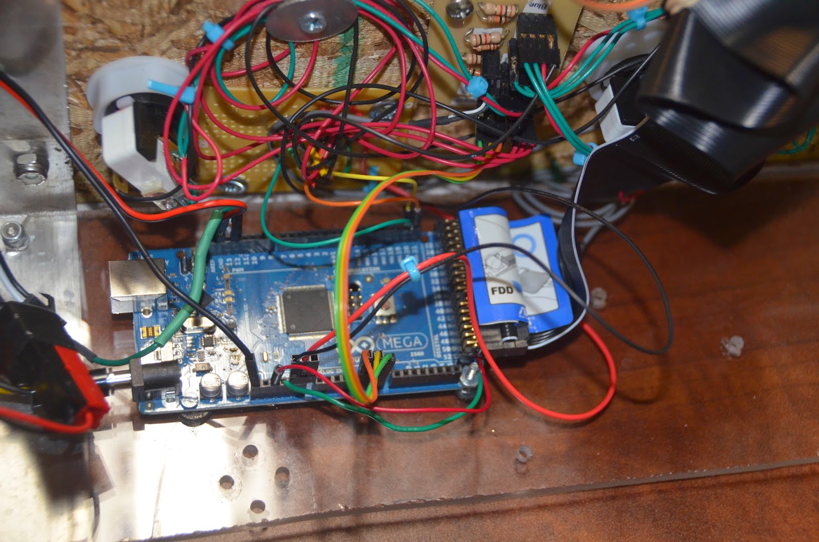
A second circuit board was hacked together when I realized that the 5V outputs from the Arduino Mega could not satisfactorily drive the LED lamps in the pushbuttons.  The outputs of this board go into the inputs for the LEDs of the previous board.  I used this webpage as a tutorial:  http://itp.nyu.edu/physcomp/labs/motors-and-transistors/using-a-transistor-to-control-high-current-loads-with-an-arduino/  .


 A couple of these LEDs seem to be systematically burning out, and I'm not sure if this is because of poor resistor selection or so other reason.  This is frustrating.  A ribbon cable was used to move pins 21 - 52 up near the LEDs, then jumper wires were used to make the connections between the ribbon cable and female headers soldered onto the LED PCB board.


For reference, here is a pinout table for the Arduino.

Green
Red
Yellow
50
30
26
45
32
28
44
33
24
46
36
BURNED OUT
43
35
23
41
34
27
48
39
25
49
37
29
47
38
31


Mega Wiring Diagram:
21… Red Transistor Board Wire
20… Yellow Transistor Board Wire
19… Green Transistor Board Wire

12… RGB Led Strip Control
GND (by #13):  Reset Switch
Reset:  Reset Switch
5V:  to Grey Cable (power to pullup resistors board)
GND:  to Grey Cable (ground to pullup resistors board)
A5:  Orange Buttons Wire
A6:  Yellow Buttons Wire
A7:  Green Buttons Wire