 |
| Figure 1 |
 |
| Figure 2 |
 |
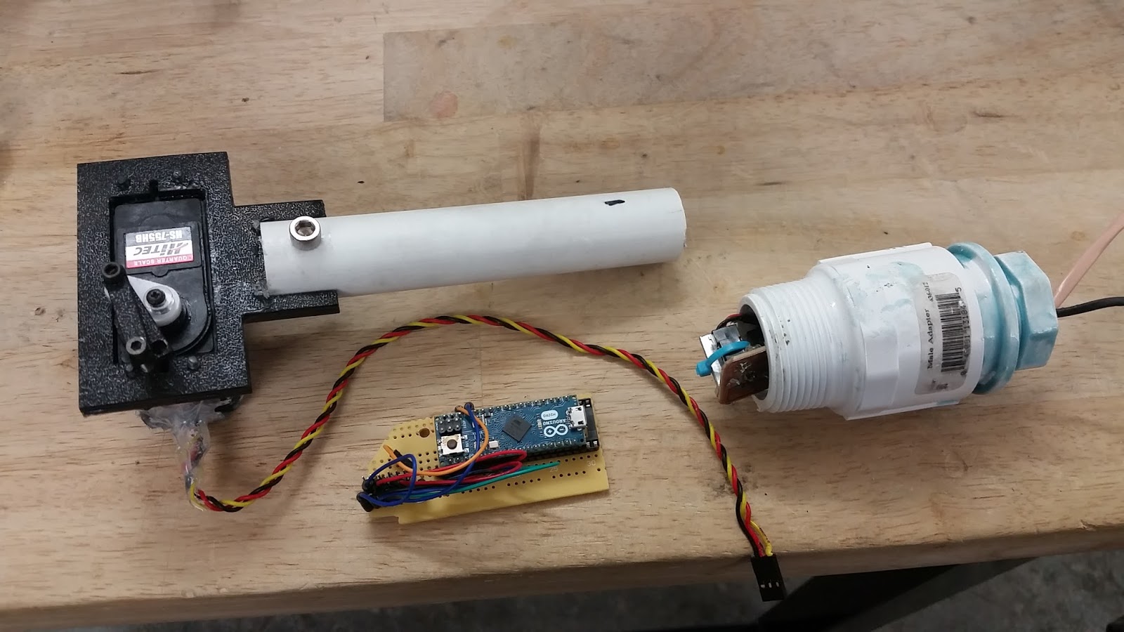
| Figure 3 |
There are a bunch of bulkhead cable connectors on the market, such as those shown in Figure 3. There are also metal ones such as this one. The idea is that you make a hole in a box, then slide the connector through the hole. The connector is sealed by compressing an o-ring when a nut is tightened. The cable itself goes through the opening in the middle and is compressed against another o-ring.
Putting those products together, I made a test enclosure shown in Figure 4. While it looked good, it still leaked over time. The bubbles could be seen coming from the bulkhead connector where it sealed with the box.
 |
| Figure 4 |
I did all my machining on the PVC with this lathe tool from MSC Direct. It is described as Accupro - 3/8 x 3/8 Inch Shank, Full Radius Cutoff and Grooving Single Point Tool Bit GS-060F, Grade Micrograin, 0.06 Inch Groove Width, 0.21 Inch Depth Of Cut.
I turned a 1.245" diameter, 1" long shoulder into the PVC. On that shoulder, I turned two grooves for o-rings. The width of the grooves was 0.16" and the final diameter of the PVC was 1.04". Each groove holds an o-ring, #214, McMaster # 9452K34, with actual width of 0.139" and actual inner diameter of 0.984".
This made for a fairly tight fit with the acrylic tubing I was initially using (part of the kit from SeaMate, part 1-ACC-1201-AA). However, it made a very nice fit with the polycarbonate I ordered from McMaster Carr, 8585K206, inner diameter 1 1/4" +/-0.050".
Testing with the plugs in the acrylic tubing showed that the container was waterproof. Testing was done by placing the container fully submerged into a large container full of water (sealed 4" ABS pipe in one case, coffee carafe in another) and letting it sit for roughly 12 hours. As various webpages note, all seals leak, so while I didn't see signs of leakage, that doesn't mean it won't happen on a real underwater ROV in real operating conditions.
I next used an 8.5mm diameter drill bit (0.3346, essentially Q size) to create through holes in the center of each of the plugs. These holes were tapped for 10mm x 1.5 and then filled with cable penetrators (here and here from Blue Robotics) with the threads wrapped in Teflon tape. I initially only did this procedure on one plug and used the enclosure vent and plug as a test to see if the hole was sealing underwater. Once it did, i installed the cable penetrator.
The last step was running the cable through the penetrator and waterproofing the penetrator. I followed the guidelines posted on the MATE website, specifically at this link: http://www.marinetech.org/module4/. They suggest using marine epoxy and sealing on both the outside and the inside. On the inside, they suggest stripping a bit of insulation from each wire in offset locations and then covering this part with marine epoxy. This prevents water from entering the container between the conductor and insulator of each strand, as shown in Figure 5. There are clearer directions here.
 |
| Figure 5 |
 |
| Figure 6 |
 |
| Figure 7 |
| Figure 8 |
 |
| Figure 9 |
The code for this project is found on Github here.