 |
| Figure 1 |
Visual Show Automation (VSA) is a software package which coordinates movement, lights, sound and video. The demo version is free at available from Brookshire Software, however it does not allow you to save files. I learned about this software from a colleague who had done a basic automation project and used this website as a starting point: http://animatronicsworkshop.com/.
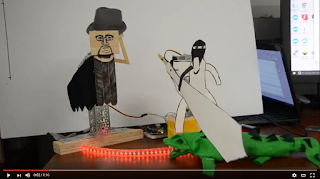
The process involves making characters which are animated by use of servo motors, recording a script, and then using the VSA software to sync up motion of the servos to the songs in the audio. IMPORTANT: if you are using the demo version, make sure the Arduino is connected to the computer before you run the software. Otherwise, you will need to restart the software and you will lose all of your work. The simple demo that is linked above using two servos and a relay to control a red light (Figure 1). The setup is done through Tools -> Settings. Use the audio tab to import an audio file (Figure 2).
 |
| Figure 2 |
 |
| Figure 3 |
Under the Device Settings tab (Figure 3), choose Disable All from the dropdown menu in the lower left corner, then reselect only those tracks that correspond to pins that you have servos or relays plugged into on your Arduino. For example, I used two servo motors with the control wires plugged into Arduino pins 2 and 5. I plugged the base of a transistor controlling a relay into pin 8. Rename the device with a logical name in the second column. The 3rd column will remain MiniSCC Servo if you are using a servo attached to an Arduino, or MiniSCC Relay if you are driving a relay using an Arduino. The fourth column needs to be the COM port that the Arduino is using. The Default (8th column) will be the starting point for the servo or relay.
From this point, when you go back to the main screen, you will see the audio waveform in the bottom. There is a tool which will automatically synchronize the motion of a servo to amplitude of the waveform. This can be found under Tools -> Waveform Analysis. For this demo, I entered servo and relay values manually.
 |
| Figure 4 |
For a servo, if you drag your mouse in the row which corresponds to the servo in the top pane, you will create a servo motion event (Figure 4). You can move the "dial" on the left to adjust the Stop Position; the servo will move in real time. When it is in the correct position, either click on Capture or manually enter the number on the left (not the angle) into the Stop Position field on the right. The Start Position is set by the previous motion event, or by the default position for the starting point. You can roughly sync up the motion to the sound waveform as you will see vertical timelines as you drag your mouse to create the event. You can drag the event to move it, or change the beginning or end times by placing your mouse over the beginning or end of the event.
 |
| Figure 5 |
A relay works pretty much the same way (Figure 5), although you only have options for on (1 output) or off (0 output). Put a 1 or a 0 in the field which is called Pulse Value.
You can copy and paste, or select different events by using the right mouse button in the top window. My demo is very repetitive, which was done using copy and paste functionality. It takes a bit of practice to get used to the interface... if you are used to dragging with your left mouse button, you will find that you are creating events instead of selecting.
 |
| Figure 6 |
On the Arduino side, the software which allows the Arduino to act like a MiniSCC is available here: http://animatronicsworkshop.com/?page_id=458. I tailored this sketch slightly to allow it to work for relays as well. The full sketch can be found on github. The picture below shows the modifications to the original sketch.

Here are a couple links to animatronic videos that were made in a class I teach. These were made without VSA, and I hope that future projects are of even higher quality.

