Thursday, May 16, 2013

Stepper Motor XY Interweave


The final task that I played with before beginning to construct a device with stepper motors and boards was the concept of making two motors move simultaneously.  This is very important when playing with 3D printers because you often want to trace out specific geometric shapes which require two motors moving in the XY plane simultaneously.  I kept it pretty simple to start by looking at how to move the "tool" in a straight line from a start point to an ending point.  I used a concept I called interweave, which basically means that you move both motors sequentially in very small increments, going back and forth to "stairstep" your way to a line.  This is shown below... the yellow motions approximate the blue line.  In the limit that the number of staircases is increased, (or to use calculus times, in the limit that the yellow step size goes to zero), the staircase becomes the blue line.
The basic idea of interweave in the way I did it, was to calculate the slope of the line, and step in small increments dx and dy which reflect the slope of the line.  This is easy to do if the slope is a whole number.  For example, in moving from position (50, 100) to position (100, 200), the slope is dy/dx = (200-100)/(100-50) = 2.  So a simple program which interweaves would have the form:

void moveSlope2Steps100()
{
  for(int i=0; i<100; i++)
  {
      takeSingleStep(YstepPin); //One step up
      takeSingleStep(YstepPin); //Second step up
      takeSingleStep(XstepPin); //One step across
    }
}

Generalizing this form is not too hard as long as the slope turns out to be a whole number... We need to know if the slope is greater than or less than one, and then we'll move more steps in the y or x direction, respectively.  Note that there are no cases here for infinite or zero slopes (eg horizontal or vertical lines).


void lineInterweaveWholenumberSlope(int deltaX, int deltaY)
{
  if(deltaX > deltaY) 
  {
     int slope = deltaX/deltaY;
     for(int i=0; i<deltaY; i++)
     {        takeSingleStep(YstepPin); //One step up
        for(int j=0; j<slope; j++)
            takeSingleStep(XstepPin); //Across number of steps equal to slope                          
     }
  }

  else 
  {
     int slope = deltaY/deltaX;
     for(int i=0; i<deltaX; i++)
     {        takeSingleStep(XstepPin); //One step across
        for(int j=0; j<slope; j++)
            takeSingleStep(YstepPin); //Up number of steps equal to slope
     }
   }
}

An example is shown below.  Suppose deltaX = 12 and deltaY = 3.    The program reduces to:


lineInterweaveWholenumberSlope(12, 3)

{
  if(12 > 3) //YES!!!
  {
     int slope = 12/3;  //4
     for(int i=0; i<3; i++)  //repeat 3 times
     {        takeSingleStep(YstepPin); //One step up
        for(int j=0; j<4; j++)
            takeSingleStep(XstepPin);//Four steps over                          
     }
  }
}


If the slope is not a whole number, then we run into issues because we cannot do moves with less than a step.  There are a lot of approaches that I considered.  Most of the early ones involved trying to convert a decimal number into a fraction made of whole numbers.  But this doesn't work because the size of the yellow staircases quickly becomes huge, or because you cannot express irrational numbers as a fraction made of whole numbers.  So the approach that I have employed is to find the nearest whole number slope, and find the remainder (modulo).  Then we can move as though we had a whole number slope, but add in extra steps to compensate for the remainder.

As an example, consider that deltaX = 14 and deltaY = 3.  Fourteen divided by three is 4.666, or we can think of it as 4 with a remainder of 2.  If we execute the same motion as described in the previous example, BUT add an extra step in the x-direction for the first two iterations, we arrive at the endpoint.   The picture at right shows the idea, with the extra steps shown in red.

It's pretty easy to code this type of behavior, because the extra step just happens as many times as the remainder.  The remainder and the slope are both easily found using integer division (the remainder is removed so int[14/3] = 4), and modulo (which records the remainder so 14%3 = 2).  Sample code for the case where deltaX exceeds deltaY is shown below.


void lineInterweave(int deltaX, int deltaY)
{
  if(deltaX > deltaY) 
  {
     int slope = deltaX/deltaY;
     int remainder = deltaX%deltaY;
     for(int i=0; i<deltaY; i++)
     {        takeSingleStep(YstepPin); //One step up
        for(int j=0; j<slope; j++)
            takeSingleStep(XstepPin); //Across number of steps equal to slope
        if(i < remainder)                          
            takeSingleStep(XstepPin); // this is the step in red
     }
  }


One thing to point out is that the extra steps mean that the actual path traced out will deviate from the ideal path; in the example above the "tool" moves too far to the right early on, but ends up in the right place.  This type of deviation is exacerbated when a) the remainder is large and b) the number of steps is small.

I created an Excel spreadsheet to explore how far off the actual line would be from the theoretical line.  The spreadsheet shows a series of points on the left corresponded to the coded actual line (based on integer slopes and modulo calculated remainders) and the theoretical points based on floating point calculations.  You can play with the number of steps in the X and Y directions to get a better sense of the errors discussed in the previous paragraph.  Here is a link to the spreadsheet.

The complete code for interweaving is below:


void moveXY(int _Xsteps, int _Ysteps)
{
  int slope[2];
  if(_Xsteps > _Ysteps)
   {
    slope[0] = _Xsteps/_Ysteps;  //calculate slope to nearest integer
    slope[1] = _Xsteps%_Ysteps;  //calculate remainder
   }
   else
   {
    slope[0] = _Ysteps/_Xsteps;  //calculate slope to nearest integer
    slope[1] = _Ysteps%_Xsteps;  //calculate remainder
   }
   if(_Xsteps == 0)  //vertical line
    {
      for(int i=0; i<_Ysteps; i++)  {takeSingleStep(stepPinY); }
    }
    else if(_Ysteps == 0)  //horizontal line
    {
      for(int i=0; i<_Xsteps; i++)  {takeSingleStep(stepPinX); }
    }
    else if(_Xsteps > _Ysteps)
    {
      for(int i=0; i<_Ysteps; i++)
      {
        takeSingleStep(stepPinY);
        for(int j=0; j<slope[0]; j++)
            takeSingleStep(stepPinX);
        if(i < slope[1]) // this is where we compensate for the remainder
            takeSingleStep(stepPinX);  //take one more step each round 

                                       //until we've taken as many as  
                                       //the remainder
      }
    }
    else
    {
      for(int i=0; i<_Xsteps; i++)
      {
        takeSingleStep(stepPinX);
        for(int j=0; j<slope[0]; j++)
            takeSingleStep(stepPinY);
        if(i < slope[1])
            takeSingleStep(stepPinY);
      }
    }
}

Stepper Motors and Drivers

PSMD Triple Axis Stepper Controller
A coworker gave me a PSMD Triple Axis Stepper motor controller about a month ago.  This is a device designed to make your life easy when building a 3D printer or something else which requires high level precision of motion in three orthogonal directions.  It provides easy connections between three stepper motors, three stepper drivers ( Polulu A4988), a microprocessor controller, and power.

The gift stimulated me to learn about stepper motors and drivers, as well as ultimately to put together a functional device which makes use of both.  While at the beginning I was shying away from 3D printing, in the end I've migrated in that direction given the wealth of information available on the subject.  This post is not about a 3D printer, but rather about the motion systems used in a 3D printer, or in any CNC machine for that matter (milling machine, laser engraver, etc).

Here's what I've learned about stepper motor drivers.  All stepper drivers activate or deactivate coils in the motors in order to step the rotor around the stator.  There are three types of stepper motors; I used bipolar motors which are common for 3D printers.  They have four wires, two of which connect to each of two sets of coils in the stator.  The rotor has permanent magnets; the number of these magnets, along with the way the coils are arranged in the stator, determines the steps to degrees turning ratio.  The stepper motors I used with the PSMD are 200 steps/turn or 1.8 degrees per step.  Stepper motors can also be microstepped so that each step moves less then 1.8 degrees.  The A4988 allows up to 1/16th of a step to be taken by changing the resistance on three pins.   Stepper motors also hold a position actively; current is constantly applied to the coils in order to stay at the current position while the motors are enabled.  There is a ton more information at this site:  http://openbookproject.net/electricCircuits/AC/AC_13.html#xtocid174388  .

All stepper motor drivers operate in current limiting mode.  This means that they turn off voltage when a maximum current has been reached.  The stepper motors that I am using for the x-axis and y-axis positioning are rated for 4V.  Yet they are being driven by a computer power supply outputting 12V.  If the 12V remains applied for the duration of a step, the motor would get too hot or could have windings burn out.  The A4988 and other similar drivers sense the current through a resistor and limit the duty cycle (amount of time) that the voltage is applied to the motor through an H-bridge, effectively limiting the average current seen by the motor.  The details are a little more complicated:

"Each full-bridge is controlled by a fixed off-time PWM current control circuit that limits the load current to a desired value, ITRIP . Initially, a diagonal pair of source and sink FET outputs are enabled and current flows through the motor winding and the current sense resistor, Rsense. When the voltage across Rsense equals the DAC output voltage, the current sense comparator resets the PWM latch. The latch then turns off the appropriate source driver and initiates a fixed off time decay mode."  See the A4988 datasheet here for more details.  

You can adjust the reference voltage, Vref (which is, I think, the DAC output voltage referenced above) using a potentiometer wired to the REF pin on the A4988 chip.  In my case, I purchased stepper motors rated at 1.2A per coil of current.  (Other important facts about the motors:  44 oz-in holding torque, and 4V rated voltage, see here for motor specs ).  According to the data sheet, Itrip = Vref/(8Rsense).  Looking at the Polulu website for the A4988, Rsense = 0.05 Ohm, so we can solve for the desired Vref = Itrip x 8 x 0.05.   With Itrip =1.2A, we get Vref = 1.2 x 8 x 0.05 = 0.48V. I set the potentiometers for this reference.  There are excellent directions online for setting up the A4988 at this URL: http://aeons.phrenzy.org/~berserk/reprap/PololuPres_V3.pdf .


All the stepper drivers which I have are controlled by three digital TTL level pins.  One controls whether the stepper is enabled or disabled.  The second controls the direction of spin of the stepper.  The third is a step pin, which initiates a step when it is pulsed high (or maybe when it drops low again... I'm not sure).  A simple function to "step" a stepper has the following form:

void takeSingleStep(int stepPin)
{
  digitalWrite(stepPin, LOW);
  delayMicroseconds(2);
  digitalWrite(stepPin, HIGH);
  delayMicroseconds(1000);
  digitalWrite(stepPin, LOW);
}


When called, this function pulses the step pin low, then high, then low again.  I found that the second delay (currently set at 1000 us = 1ms) is important; if that delay is too small then the stepper doesn't have time to execute multiple steps sequentially and it makes weird noises and moves erratically.

A simple function which turns on or off the stepper motors is shown below.

void enableStepperXYZ(int isEnabled, int enablePin)
{
  if(isEnabled)
       digitalWrite(enablePin, LOW); // enable HIGH = stepper driver OFF
   else
      digitalWrite(enablePin, HIGH); // enable HIGH = stepper driver OFF
 
  delayMicroseconds(2);
}


Two simple set of functions which change the direction of rotation are shown below.  I found that one way did not work for the v3.3 driver; they are labelled appropriately.

The following function worked for only the PSMD and is an absolute function:  it sets the direction either clockwise or counterclockwise.

void setCurrentDirection(boolean dir, int dirPin)
{
  if(dir == false)
      digitalWrite(dirPin, LOW);
  else
      digitalWrite(dirPin, HIGH);
  

  delayMicroseconds(1);
}


The following two functions worked for both boards and are relative functions:  they set the direction to be opposite the previous direction.

boolean currentDirectionZ = true;

void setCurrentDirectionZ(boolean dir, int dirPin)
{
  if(dir == false)
      digitalWrite(dirPin, LOW);
  else
      digitalWrite(dirPin, HIGH);
 
  currentDirectionZ = dir;
  delayMicroseconds(1);
}

void changeDirectionZ()
{
  setCurrentDirectionZ(!currentDirectionZ, dirPin);
}


Besides the step, enable, and direction pins, there are other pins on the A4988 which are important, but the PDMS board takes care of most of them for you.  For example, the reset and the sleep pins are both pulled high, effectively making them unusable but so you do not need to worry about them.  The board has three mini-switches attached to MS1, MS2, and MS3, which allow you to easily set the stepping mode (full, 1/2, 1/4, 1/8 or 1/16).

MakerBot v3.3 Stepper Driver
I also worked with the StepperDriver3.3 from Makerbot as there were several of those sitting around from previous work done by others on Makerbot3D printers.  The documentation for these has been largely pulled from the web since they are older products, but they are totally functional.  I've posted the relevant file here.  Most of the information is really similar to the PSMD board, because the v3.3 is based off of a predecessor chip to the A4988, the A3977.  Here's the datasheet for the A3977 chip.  If you compare the two datasheets, you'll see that they are essentially the same at the level of detail that I have been talking about.   One difference is that the A3977 does not have 1/16th stepping possibility, only full, 1/2, 1/4 and 1/8th, set by two pins, MS1, and MS2.  A second difference is that the A3977 supports higher currents and therefore bigger motors, with a rated current of 2.5A compared with 2A for the A4988.


I used the v3.3 board with 42BYGHW-811 Wantan stepper motors, which are rated to a higher current of 2.5A.  The Rsense resistors are 0.25 Ohm for this board, so with a rated current of Itrip = 2.5A, we can calculate the value of Vref to set for the v3.3 board as 5V.  The maximum permissible for the logic of the A3977 circuits is 4V according to the datasheet, so I set Vref = 4.0V.

The PSMD board also has integrated pinouts for limit switches, which are sometimes used to detect the end position in the X, Y, and Z axes (both low and high limits).  The pins provide +5V, and a signal pin.   You can digitally read the signal pin to see when it is shorted to ground with a pullup resistor enabled on the Arduino.


v3.3 Cable Ribbon Pinout
PSMD Cable Ribbon Pinout
Wiring up the stepper motor boards to an Arduino is very easy to do if you have some ribbon cable and the pinout diagrams for each board.  The pinout are shown here... I wired together the enable pins for all the steppers into one pin on my Arduino allowing me to turn on and off all the motors at once.


Saturday, April 20, 2013

Turret Gun Robot - iPhone Control

The turret gun robot is up and running in a "teleoperated" mode using an iPhone as the controller.  The built in accelerometer on the iPhone has been mapped to control the drive motor powers.  As noted before, the OSC connection seems to work fine as long as the bug involving the motor power is screened out.  The Processing interface reports the sensor data (two encoders, three IR distance sensors, and a 6DOF gyro/accelerometer), shows the motor powers derived from the tilt of the iPhone, shows the gun status as on/off, and shows the pan/tilt of the turret by both printing the values and mapping them to a target bulls-eye   When Processing is set to 3D mode, the gyro values are mapped to a rotating cube which shows the orientation of the robot.  Since the robot can only rotate around a single axis, the cube rotates around the x-axis.  There are two movies below which show the processing sketch in 2D mode, then in 3D mode.

Processing in 2D Mode.

Processing in 3D mode:  Watch the rotating rectangle.
This project has been a long time in the making so I am very proud to have gotten this far.  The robot is pretty dumb for the amount of sensors it has, so I'll have to work on making it smarter.

Here is the link to the Arduino Code.  Note that I turned off the stall checks as they were giving false positive too often.  I will have to work on figuring out why that is.


Sunday, April 14, 2013

Useless Box with No Button


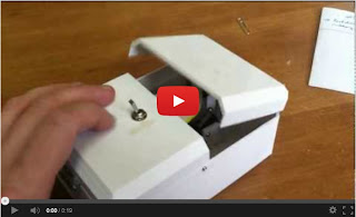
This is another useless box, but this time I incorporated a "No Button" which my parents had given me for X-mas.  The button just says "No" in one of many different ways when it is pressed.  I figured this would be easy to rig with the existing momentary switch on the inside of the box so that it would say "No" when the box was turned on and as it was turning itself off.

Two battery systems power the motor and the No Button.
The speaker is in the top right corner.
Whenever integrating ideas like this, one has to make sure of compatibility   For instance, the GM3 motor is running off of 6V, but the No Button runs off of 3V.  Should those two be integrated or left separate?  In this case it was much easier to leave them separated.  A voltage divider was something I considered, but the voltage will fluctuate as the GM3 motor turns and also as the No Button circuit draws current.  In addition, the voltage divider would be constantly shunting current from the batteries unless a separate on/off switch was installed, which seemed to defeat the purpose of the useless box.

Here you can see the two momentary switches
which are both tripped by the wooden arm.
Another compatibility question was whether the same momentary switch could be used to drive both the GM3 and the No Button.  This would be very convenient, but it turned out not to work.  Instead when the motor was running, the No Button generated static which persisted even after the momentary switch was opened again.  Perhaps some capacitance and some IC effects on frequency?   Anyhow, after brainstorming, I realized that it would be very easy to add a second momentary switch right next to the first so that the arm would trip both switches at the same time.  In this way, the No Button is completely isolated electrically from the motor circuit, and it works great.

Monday, April 8, 2013

Useless Box

I've been wanting to make a useless box since I saw several postings on Make Magazine's website.  I decided to make two for an auction for a choir that I sing in called the Northwest Chamber Chorus.  I based the design completely off one found on Thingiverse, using the author's .stl files to generate gcode for our Replicator 1.  Thanks so much jamesarm97!!!  The only thing I modified was the arm (dxf file here).  I made one in white and one in black.


Parts List:


This is how to wire the DPDT
switch.  Looking at the bottom.
The wiring that makes this work is fascinating and really clever.  The DPDT reverses the polarity of the battery that the motor sees when the switch is thrown.  In addition, one leg of the circuit has a momentary switch in series with the motor.  The momentary switch is soldered so that it is normally closed, but opens when the switch is pressed.

Picture taken from Pombo on
thingiverse:
http://www.thingiverse.com/thing:12021
In the "all off" position shown at right, the momentary switch is pressed so no current flows (top illustration).  When the DPDT switch is thrown, the motor is now in series with the battery and swings the arm counterclockwise (middle illustration).   As soon as the arm begins to move, the momentary switch is now unclicked and so it is shorted.  

When the arm  hits the DPDT switch and pushes it "off", the motor is now in series with the battery but with the opposite polarity, so it begins to rotate in a clockwise direction.  This happens until it contacts the momentary switch, which then opens the circuit.  This loop repeats every time the power button is pressed.


Once all the parts were printed, it was basically just a matter of assembly.  I had to try several designs for the arm until I found one which worked, but it was not very difficult.

Friday, March 22, 2013

Calculator

I had an LCD (LMB0820, available from Seeedstudio, datasheet link here) that I wanted to try out, and in conjunction with a keypad (96BB2-056-R Grayhill, available from Digikey, datasheet link here), I thought it would be interesting and easy to make a calculator.  It turned out to be a whole lot more challenging that I thought.


The electronics for this project was fairly straightforward.  The LCD has eleven pins to wire up, so in conjunction with the eight for the keypad, this project used up all but one of the I/O pins on a Arduino Duemilanove.  I also wired power through a switch on the front.  Incidentally, I found out not to use pin13 for the keypad.  Apparently the resistor required for the built-in LED messes you up!  Pin 13 worked fine for the LCD though.  This word document lists the Arduino pins used for the Keypad and for the LCD.

The hardest part of this project was most definitely the coding aspect.  


I started by reading in pressed keys into a character array, displaying each key on the top line of the LCD by simply moving the cursor to the right one time after each button was pressed.  The numbers are stored in an 9 element char array (last character is a null character) which limits the size of input numbers to 8 characters.  Numbers are added to the last element in the array, shifting every other element to the left first.  This is important, because if the input buffer has the following form: {'0','0','0','0','0','0','3','4',null}, it will convert easily to the number 34.  Conversely, if you were to read in characters from the left side, {'3','4','0','0','0','0','0','0',null}, you would obtain the value 34,000,000 when converting to a number. 

I later added support for negative numbers (which now limited the size of input numbers to 7 characters as the first character location on the top LCD line is reserved for the negative sign).  I also added a decimal button.  Fortunately, the built in function "atof" converts a char array of the form {'-','0','0','0','0','0','3','4',null} to -34, and a char array of the form {'0','0','0','2','.','0','3','4',null} to 2.034. 

I used two buttons on the keypad as up/down scroll keys, moving through a list of functions that I added.  Currently the calculator supports addition, subtraction, multiplication, division, powers, squaring, and tangent, cosine, sin.  But it would be pretty easy to add other functions in.  A mod function makes the scrolling effortless.
The approach that a calculator takes depends on whether the mathematical function desired takes one or two numbers.  The trig functions and squaring require only a single number, while the other functions require two numbers.   The first time the "equals" sign is pressed, the program stores the first number (using the built in function "atof" which maps a character array into a floating point variable) and the desired function.   The program prints an error message "FUNCT??" if the user does not have a function selected when the "equals" key is pressed.

If a single number function is selected, the code executes the function and prints the result.  Otherwise, the code clears the top line on the LCD and "zeros" the input buffer to make room for a second number.  The second time the "equals" sign is read, the code reads the second number, executes the function, and prints the response. 
There are several inherent difficulties with a calculator.  The first has to do with the limited size of an LCD display.  This is a problem for both inputs and outputs.  For inputs, I chose to simply limit the program to a maximum number of input digits.  Additional pressed buttons are just not registered.   Otherwise one would have to treat memory more dynamically, allocating arrays to fit the size of the input numbers.  This would be much more efficient, but I don't know how to use malloc at this time.  Also, the top line of the display would need to scroll to allow the user to see what had already been inputed as well as what they were inputing currently.  This was not worth the work.

In terms of outputs, we have two potential problems.  The first is if the result of the calculation is bigger than eight characters.  My code returns "too big" if the result exceeds 99999999 or is less than -9999999.  The second problem is if the number is too small.  Currently the code always prints 4 decimal places, so if the response is less than 0.0001 but greater than zero, then the code prints "too small".   Better programs would implement scientific notation of some type.

I worked to make the interface clean, although it still needs more work.  I added a function which parses the output to find the decimal place.  It reads the values after the decimal place and decides the number of decimals to print by discarding any trailing zeros.  Hence, the result of 25/5 is printed as 5 (not 5.0000), while 6/5 is printed as 1.2 (not 1.2000), 6.1/5 is printed as 1.22 (not 1.2200), and so forth. 
If the user wants to use a function which needs a second number, I added code which shows what has been input on the second line.  

I also added code which keeps a running string which includes the first number pressed, the function pressed, the second number pressed, and an equals sign (for functions which work with two numbers) OR the first number pressed and the function pressed plus an equals sign (for functions which work on a single number), then displays this string on the top line.  The top line will scroll to the left continuously if the string is too long to fit on the LCD line.

I thought that it would be fun to use the calculator as a "game".  So I added an initialization routine which asks the user to choose between calculator and game mode.  In game mode, when you enter a number and press "Enter", it executes a function on the number and returns the result.  The user has to guess the function by trying to figure out the rule being applied to the numbers.  See if you can figure out the rule from the movie below.

It would be easy to add more functionality to the game such that there were different levels with increasingly harder functions, or even functions which act on two input numbers.  

The code has some issues with precision in floating point arithmetic; when I compare the results from a TI-83 calculator to the results of the Arduino calculator, they sometimes differ in the last digit.  It is a little buggy; I've seen weird characters displayed on the LCD and it has frozen a couple of times on me.   Despite these issues, and the obnoxious usage of the "equals" button, the calculator works pretty well.  I'm sure I will clean up the bugs over time.

When I have time, I will add a new overlay for the keypad which shows more clearly how to use it (eg up and down arrows, an equals key, +/- key, and decimal key). 


Monday, February 11, 2013

Turret Squirt Gun: Built!!!

The turret squirt gun has been built!!!  The process went really well with one major hurdle and breakthrough.  My goal was to build a tough and reliable mechanical system which would allow a focus on programming.  I really pushed myself for a clean design which was completely visualized ahead of time using CAD, making the building relatively easy.  The chassis was constructed from the Microrax system, http://www.microrax.com/, which consists of 10mm square aluminum extrusions with M3 nut plates and brackets used to fasten bars together.  I looked into the OpenBeam system as well, but the extrusions for that system were 15mm square, which was bigger than I needed for this project.


I bought the tank and tread system from Tetrix, which comes with six idler wheels for the bottom of the robot, and two sprockets which get driven by the motors.  The tetrix system uses 4.7mm nonstandard axles with a flat on them.  Axle lockers are used to keep things from moving.  From experience with them, they are great for prototyping but they are terrible for permanent installations.    I wanted a very low friction, reliable setup, so I used ball bearing mounts from Open Beam, 8mm bearings, 8mm bolts, and skateboard spacers, to mount the idler wheels between two pieces of the Microrax.


I planned carefully to fit all the electronics in an enclosed box, given that the squirt gun was going to be directly above the electronics.  The Microrax setup allows for acrylic panels to be easily slid into place, so I planned carefully on the placement of the arbotix, two parrallex HB25s, the battery, the RX64s, my relay board for the squirt gun, and a new addition which was a 6DOF (degree of freedom) accelerometer and gyro I2C board from Sparkfun.  I needed a little electronics board for the 6DOF, because it runs off 3.3V while the Arbortix board is a 5V device.  I used an LM317 to bridge the voltage gap between those two.  Interestingly, a simple voltage divider circuit did not work... perhaps the voltage was not stable enough for the electronics... the regulator was a necessity.
In the middle, you can see the 6DOF screwed into the piece of white acrylic.  The relay which drives the squirt gun is just behind a tiny blue capacitor.

Actually the battery did not fit where I had originally envisioned, which was ok.  The relay board for the squirt gun and the 6DOF board (those two were attached to each other) took up a lot more space than I had planned.  Fortunately, the battery fits great at the back of the robot where it is easily accessible for charging.


Here you can see that the motor barely clear the
acrylic enclosure. 


Pretty much everything went together the way that I wanted.  One difficulty was that the motors had to be mounted slightly higher than I had originally envisions in order an acrylic plate that was the top of the enclosure for the electronics.  Another difficulty was that I needed to mount Microrax on top of each other and at right angles in order to provide structural integrity across the entire robot in the direction perpendicular to the tank tracks.    This required fabricating and 3D printing a part.  I used SolidWorks to create the part, exported the part as an STL file, cleaned up the part using NetFabb, generated gcode using Replicator G, and then printed the part out of polylactic acid (PLA) on a Replicator.  The CAD as well as a picture of the printed part are shown below.


The other piece of this puzzle that was extraordinarily difficult came out during testing.  When I ran the program, it started going back to the random glitch I had seen previously when trying out the iPad as a control device over OSC.  Fairly regularly, the motors would both spin, the tilt servo would move, and the gun relay would trip.  This all lasted for maybe half a second before going away.  I had previously assumed that the problem had something to do with the OSC/iPad setup, but clearly with that removed from the loop and the problem still occurring, I had been wrong.

Originally the glitch went away when the Xbees were replaced with an FTDI cable.  So clearly the problem had something to do with serial communication over the Xbees.  I tried to move the Xbee to a more central location away from the metal aluminum, which might have been screwing up with the radio waves.  This did not fix the problem.  If the Xbees were the problem, then the Arduino sketch would need to be modified to detect an anomalous serial packet, and to ignore it.  I tried multiple conditions, such as if(gun == 1 && tilt > 465 && motor1 > threshold && motor2 > threshold).  If that criteria was met, I set the "error" flag in my program equal to one.  After many many trials, I was able to screen out the problem by looking for motor powers in positive or negative direction above 90% power.  Setting the error flag when this occurred removed the glitch.  I modified the Processing sketch so that it no longer sent powers this big.

There is a lot to be done still on the robot, but at this point I can focus on programming.  Here are the future projects:

  • Get the stall check code working repeatably
  • Revisit the iPad/OSC control and see if it works repeatably with the "glitch" being screened out
  • Calibrate the gyro/accelerometer to do repeatable turns of known angle
  • Calibrate the optical encoders to move repeatable set distances in a straight line
  • Start playing with autonomous code to detect and react to obstacles based on the infrared sensors